Advertisement
Quick Links
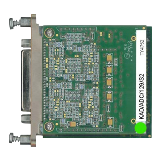
KAD/ADC/129/S2
Full-bridge ADC (voltage excitation, programmable analog gain,
sense lines, 25kHz b/w) - 4ch at 100ksps
Key Features
•
Four full or ½-bridge, potentiometer or
differential ended input channels
•
Programmable input range (±10mV to ±10V)
•
High accuracy (0.02% FSR typical for range of
1V and 10V)
•
Programmable voltage excitation with
separate sense lines and balance adjust
•
Short on any channel does not affect others
•
16-bit simultaneous sampling on each channel
Applications
•
Bridge sensors and strain gage measurement
•
Differential voltage measurement
INFO: CURTISSWRIGHT.COM
EMAIL: DS@CURTISSWRIGHT.COM
1 Jun. 2021 | DST/V/081
Overview
The KAD/ADC/129/S2 has four channels of signal conditioning and data
acquisition for differential voltages, strain gage or bridge measurements.
In addition to the measurement channel, the KAD/ADC/129/S2 provides
independent bipolar excitation for up to four channels. Each differential
ended signal has a separate programmable amplifier, filter and A/D
converter.
At the heart of the KAD/ADC/129/S2 is a hard-wired state-machine that
over-samples all channels at a rate between 200ksps and 400ksps and
digitally filters any noise above the user-programmable cutoff frequency.
This is achieved using cascaded, half-band, decimate by 2 x 15-tap,
Finite-Impulse-Response (FIR) filters followed by an 8
Infinite-Impulse-Response (IIR) filter with a default cutoff point set at a
quarter of the sampling frequency. All signals are sampled simultaneously.
Thus, when several channels are sampled at different sampling rates, all
channels will be aligned at the start of an acquisition cycle.
The KAD/ADC/129/S2 is intended for use with strain gages, and should
not be used for asymmetric bridge transducers such as accelerometers,
pressure transducers unless sensor re-calibration is carried out on a
channel-by-channel basis. If the sense lines or internal offset adjust
(balance feature) are not required, refer to the KAD/ADC/129/S1.
SENSE(0)+
1
-
EXC_V(0)+
2
+
+
5
ANALOG(0)
4
-
+
EXC_V(0)-
3
-
SENSE(0)-
6
51
GND
Figure 1: First of four channels on the KAD/ADC/129/S2
+
-
GAIN [1, 10, 100, 1000]
+
ANALOG
DIGITAL
-
AAAF
INST. AMP
-
+
V ADJ
34.8K [R ADJ ]
CURTISSWRIGHTDS.COM
th
order Butterworth
DIGITAL
ANALOG
V REF
COUNTS
UNITS
DIGITAL FILTER
LOOKUP TABLE
DIGITAL
ANALOG
KAD/ADC/129/S2
KAD/ADC/129/S2
1
Advertisement

Summary of Contents for Curtiss-Wright KAD/ADC/129/S2
- Page 1 A/D converter. Key Features At the heart of the KAD/ADC/129/S2 is a hard-wired state-machine that • Four full or ½-bridge, potentiometer or over-samples all channels at a rate between 200ksps and 400ksps and differential ended input channels digitally filters any noise above the user-programmable cutoff frequency.
- Page 2 KAD/ADC/129/S2 Specifications All values provided in the following specification tables are valid within the operating temperature range specified under “Environmental ratings” in the “General specifications” table. Module specifications are met for up to 97% of Full Scale Range (FSR). TABLE 1...
- Page 3 KAD/ADC/129/S2 TABLE 2 Differential ended analog inputs (continued) PARAMETER MIN. TYP. MAX. UNITS CONDITION/DETAILS DC error DC signal averaged over 200 samples without excitation. gain = 1, 10 – 0.02 0.08 %FSR gain = 2, 20 – – 0.14 %FSR gain = 4, 40 –...
- Page 4 KAD/ADC/129/S2 TABLE 2 Differential ended analog inputs (continued) PARAMETER MIN. TYP. MAX. UNITS CONDITION/DETAILS Filter delay – – µs Where f = 10kHz (f : input signal frequency). Input resistance between inputs – – MΩ Whether module powered on or off.
- Page 5 KAD/ADC/129/S2 TABLE 4 Balance current outputs PARAMETER MIN. TYP. MAX. UNITS CONDITION/DETAILS Outputs – – – Applied per channel. Connected internally with corresponding ANALOG(x)- input. Output current operating range – µA resolution – – DC error error – – %FSR With a constant 175Ω...
- Page 6 KAD/ADC/129/S2 Setting up the KAD/ADC/129/S2 http://www.xidml.org All module setup can be defined in XML using XidML® schemas (see Instrument settings SETUP DATA CHOICE DEFAULT NOTES Manufacturer Name ACRA CONTROL ACRA CONTROL Name of manufacturer. PartReference KAD/ADC/129/S2 KAD/ADC/129/S2 The instrument part reference.
- Page 7 KAD/ADC/129/S2 Getting the most from the KAD/ADC/129/S2 Wiring configurations Figures 2 to 4 show possible wiring configurations for the KAD/ADC/129/S2. SENSE(1)+ EXC_V(1)+ DIGITAL ANALOG V REF GAIN [1, 10, 100, 1000] ANALOG(1)+ ANALOG COUNTS DIGITAL UNITS ANALOG(1)- AAAF INST. AMP...
- Page 8 Excitation drift on potentiometer configurations Curtiss-Wright recommends a full-bridge input configuration for the KAD/ADC/129/S2. With this configuration the differential input amplifier removes common mode voltage or common mode pickup noise on the input lines. For potentiometer circuits where the negative input is tied to ground, excitation drift can have a direct impact on the input signal either as a gain or an offset error.
- Page 9 KAD/ADC/129/S2 The DC error specification is checked as a differential input, so it does not include loading by R which causes an additional gain error. In the previous figure, the gain error only occurs when the active leg of the bridge is connected to ANALOG(x)-. In this situation, ANALOG(x)- is loaded by R , forming a resistor divider with the resistance of bridge visible from the ANALOG(x)- input.
- Page 10 KAD/ADC/129/S2 milliseconds Figure 6: Filter delay for 8 order Butterworth filter where f = 1kHz The filter delay for the KAD/ADC/129/S2 is: Butterwort is the filter delay (analog filter delay) 0 Additional delay sources Primary gains higher than 10 cause an additional delay from 1 order filters in the instrumentation amplifier.
- Page 11 KAD/ADC/129/S2 Connector pinout of the KAD/ADC/129/S2 NAME SEE SPECIFICATIONS TABLE COMMENT SENSE(0)+ Bipolar DC voltage excitation outputs Sense line from top of bridge EXC_V(0)+ Bipolar DC voltage excitation outputs Excitation to top of bridge EXC_V(0)- Bipolar DC voltage excitation outputs...
- Page 12 Confirmation of Order unless an alternative option is specified (see the Cables data sheet). The KAD/ADC/129/S2 uses power from the ±7V power line for excitation and therefore cannot be used with KAM/CHS/04L, KAM/CHS/05F, KAM/CHS/03F, or KAM/CHS/02F.


Need help?
Do you have a question about the KAD/ADC/129/S2 and is the answer not in the manual?
Questions and answers