Table of Contents
Advertisement
Quick Links
Advertisement
Table of Contents

Related Manuals for Curtiss-Wright SSR/CHS/001/B


Summary of Contents for Curtiss-Wright SSR/CHS/001/B
- Page 1 Multi-role Recorders User Guide...
-
Page 3: Table Of Contents
ABLE OF CONTENTS ......................1 ELCOME About this Multi-role Recorders User Guide ................1 Unpacking and checking the contents ..................1 Registering for technical updates .................... 2 Getting help and support ......................2 ..................3 ARDWARE INSTALLATION ESD considerations ......................... 3 Multi-role recorder connectors .................... - Page 4 Multi-role recorder front panel features .................. 13 START/STOP switch......................13 EVENT button ........................13 Alphanumeric display ......................13 Status LEDs ........................14 Navigating display settings ....................15 Viewing current configuration....................16 Preparing memory media ...................... 18 Formatting memory media using a multi-role recorder ............18 Formatting a SATA SSD using the SSRFormat utility............
-
Page 5: Welcome
DAS Studio 3 setup software is included free of charge with the multi-role recorder purchase. In this Multi-role Recorders User Guide, we use an SSR/CHS/001/B multi-role recorder as the example for drawings and procedures. Where a drawing or procedure differs from the SSR/CHS/001/B, refer to the respective multi-role recorder data sheet. -
Page 6: Registering For Technical Updates
Visit www.cwc-ae.com for further information about the company’s products and for resources such as FAQ, technical notes and tutorials. Please provide details of any hardware or software problems you have to Curtiss-Wright support (acra- support@curtisswright.com). Multi-role Recorders User Guide (HW/BK/0034 | 12 Oct. 2021) -
Page 7: Hardware Installation
This chapter describes the connecting of devices to a multi-role recorder, establishing ground, and installing a multi-role recorder in an aircraft. In this Multi-role Recorders User Guide, we use an SSR/CHS/001/B multi-role recorder as the example for drawings and procedures. Where a drawing or procedure differs from the SSR/CHS/001/B, refer to the respective multi-role recorder data sheet. -
Page 8: Multi-Role Recorder Connectors
Multi-role recorder connectors This section describes connecting typical devices to a multi-role recorder. The following figure shows the connectors on an SSR/CHS/001/B multi-role recorder. 6-way power Ground mounting connector bolt 19-way (Mighty Mouse) connector 10-way (Mighty Mouse) Ethernet connector Voice connector... -
Page 9: Connecting The 19-Way Interface
On first-generation multi-role recorders the voice signal is taken through the 19-way I/O connector. On the SSR/CHS/001/B (and all subsequent multi-role recorders) the audio connector is a separate voice connec- tor (see “Connecting the voice interface” on page 5). -
Page 10: Installing/Removing Memory Media
Installing/removing memory media It is not required to disconnect power when inserting or removing media. Never force a CompactFlash™ card (CF card) or SATA Solid-State Drive (SSD) into the multi-role ARNING recorder; forcing media into multi-role recorders can damage the media and the multi-role recorder pins. When no media is inserted, the ERROR LED is on. -
Page 11: Installing/Removing A Sata Ssd
Installing/removing a SATA SSD To prevent incorrect insertion, the media and housing are keyed. To open the media door, push and turn the handle counter-clockwise. Do not push here; doing so prevents the media handle from turning easily Insert the SATA SSD firmly until it is flush with the housing. Close the door, then push and turn the handle clockwise. -
Page 12: Multi-Role Recorder Grounds
Multi-role recorder grounds The multi-role recorder has the following three grounds: • GND: internal electrical ground • CHASSIS: mechanical ground • POWER(-): 28V return All three grounds are isolated from one another inside the multi-role recorder. GND is the zero volt line that all internal signal conditioning modules use. All input and output signals on the multi- role recorder are referenced to this potential. -
Page 13: Replacing The Rtc Battery
POWER(-) POWER(-) CHASSIS CHASSIS Power Multi-role recorder Power Multi-role recorder Star Point Figure 3: Grounding for multiple multi-role recorders Replacing the RTC battery Some multi-role recorders have a Real-Time Clock (RTC), which keeps time when the multi-role recorder is not connected to a power source. -
Page 14: Installing A Multi-Role Recorder In An Aircraft
Figure 4: Installing an SSR/CHS/001/B For the bend radius measurement of NET/CON/00X cables, see the Network cables data sheet. For the bend radius measurement of cables connecting to any installed modules, see the Cables data sheet. -
Page 15: Perating A Multi - Role Recorder
This chapter provides an overview of the functionality, configuration, and operation of a multi-role recorder. In this Multi-role Recorders User Guide, we use an SSR/CHS/001/B multi-role recorder as the example for drawings and procedures. Where a drawing or procedure differs from the SSR/CHS/001/B, refer to the respective multi-role recorder data sheet. -
Page 16: Third Party Snmp Tools
Navigator Editor Figure 5: DAS Studio 3 main screen Multi-role recorders support a range of configurable plug-in user-modules. From these configuration settings, DAS Studio 3 determines the optimal packetization properties required for recording and transmitting the data. Both the plug-in user-module settings and the packet formats are stored in the XidML metadata generated by DAS Studio 3. For more information, see TEC/NOT/067 - IENA and iNET-X packet payload formats. -
Page 17: Wireshark
SNMP tools. For more information on SNMP settings used with a multi-role recorder, see “Using SNMP” on page 22. For a copy of the MIB text file, contact Curtiss-Wright support (acra-support@curtisswright.com). Wireshark Data recorded using a multi-role recorder is stored in PCAP format. You can view the PCAP files using a network protocol analyzer such as Wireshark. -
Page 18: Status Leds
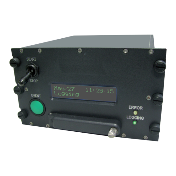
Status LEDs The LOGGING LED lights green when recording is taking place. When the ERROR LED lights yellow, recording is not possible. The ERROR LED lights yellow under the following conditions: • The memory media is not inserted. • The memory media is not recognized or not mounted. •... -
Page 19: Navigating Display Settings
The following figure illustrates various displays found using the EVENT button and START/STOP switch. Buttons: Connect power START: Switch in the START position STOP: Switch in the STOP position EVENT SSR/CHS/001/B ERROR LED ACRA CONTROL LOGGING LED May/28 13:46:49 Press EVENT... -
Page 20: Viewing Current Configuration
The display settings shown in Figure 7 on page 15 Figure 9 on page 17 apply to both SATA-based and CF card-based multi-role recorders. When an SSR/CHS/001/C is installed but is not recording data, the data rate seen by the recorder is shown on the bottom right of the display as a percentage of the 40 Mbps nominal logging speed (see the following figure). - Page 21 View configuration IP Address: 192.168.28.1 Press EVENT MAC Address: 000C-4D-56-78-9A Press EVENT IP Mask: 0.0.0.0 Press EVENT Brightness: 100% Press EVENT Wraparound: Enabled Press EVENT When set to PTP, the display shows PTP: In-Sync. PTP: When set to GPS or IRIG, In-Sync the display shows Press EVENT...
-
Page 22: Preparing Memory Media
Preparing memory media Memory media must be formatted before it is used. SATA SSD can be formatted either on the multi-role recorder itself, on insertion of the media, or externally using the SSRFormat utility; CF cards can only be formatted on the multi-role recorder. -
Page 23: Using Media Space Effectively
Currently, network recorders do not support the TRIM command and it is no longer required on DRE/SSD/003 and later models. Using media space effectively For information on the files created and space management, see “File formats and management” on page Recording data This section describes methods for controlling recording, using the wraparound function, and recording events. -
Page 24: Recording Data With Wraparound
Local control using the front panel Before you can control the multi-role recorder locally using the front panel START/STOP switch and EVENT button, you must set controlMethod to local (0). At any time, move the START/STOP switch to the START position to record, or move it to the STOP position to stop recording. -
Page 25: Recording Events
Press the EVENT button anytime while recording to place a bookmark. An event bookmark is an event packet, which marks a place in the recording. To stop recording, move the START/STOP switch to the STOP position. For more information, see “Viewing recorded files on a PC”... -
Page 26: Using Snmp
May/28 09:36:42 Time left 15 hours N000 Hours 15 May/28 09:58:42 Time left N000 Mins 15 15 minutes May/28 11:30:42 Time left N000 Secs 118 118 seconds Figure 12: Remaining time displays Using SNMP Use an SNMP browser to access the SNMP variables. For information on SNMP variable definitions, see TEC/NOT/058 - Overview of SNMP and using third party SNMP tools and the MIB text file. - Page 27 Setting this variable to 0 disables Ethernet recording but it does not disable Ethernet packets from the SSR/CHS/001/B; setting it to 1 enables Ethernet recording. Both the recorded Ethernet and multi-role recorder data packets are stored in a PCAP file format.
-
Page 28: File Formats And Management
For details, refer to the “Setting the multicast address filter” table in TEC/NOT/069 - Xbar Switches - Filtering and Forwarding and the appropriate multi-role recorder data sheet for details on the number of filters and filter types available. The multi-role recorder does not support the use of multicast IP addresses of the format XXX.0.0.0. File formats and management Formatting the media creates pre-allocated empty files for storing recordings in a flat directory structure. -
Page 29: Efficient Space Management
Power loss while recording If the recorder loses power while recording, the File Allocation Table (FAT) does not have time to be updated. When opening the files in Wireshark, an error is displayed, even though no packets are actually missing or corrupted. -
Page 30: Viewing Recorded Files On A Pc
Viewing recorded files on a PC The media used in a multi-role recorder supports a FAT32 file system so that when the media is mounted on a standard Windows PC, the files can be instantly viewed in Explorer. When the media is mounted locally on a PC, it is possible to browse the following information: <date>... -
Page 31: Processing And Extracting Inet-X Data From Recorded Pcap Files
Processing and extracting iNET-X data from recorded PCAP files Since the PCAP file contains packets generated by each of the user-modules, it may be necessary to extract individual module data for a specific stream ID. Consider a PCAP file containing recorded data with multiple stream IDs generated by several user-modules in the multi-role recorder. - Page 32 This page is intentionally blank...
- Page 33 Curtiss-Wright makes no warranty of any kind with regard to this material, including but not limited to, the implied warranties or merchantability and fitness for a particular purpose.
- Page 34 Curtiss-Wright www.curtisswrightds.com 15 Terry Drive Block 5, Richview Office Park Newtown Clonskeagh PA 18940 Dublin 14 Ireland Phone: 1.267.352.2020 Phone: 353.1.295.1264 © 2021 Curtiss-Wright...
Need help?
Do you have a question about the SSR/CHS/001/B and is the answer not in the manual?
Questions and answers