Advertisement
Quick Links
SSR/CHS/001
Ethernet multi-role recorder (CompactFlash®, voice connector) - 4
user-slots
Key Features
•
Rugged CompactFlash-based 100BaseTX
Ethernet recorder
•
Built in GPS, digital IRIG-B, PTPv1 and PTPv2
synchronization including Grandmaster
•
Battery-backed up time
•
Operating range of -40 to 85
•
Up to 40 Mbps logging speed
•
Fat 32 file system
•
Four user slots for plug-in modules
Applications
•
Data logging and/or muxing
INFO: CURTISSWRIGHTDS.COM
EMAIL: DS@CURTISSWRIGHT.COM
24 Nov. 2020 | DST/AE/022
Overview
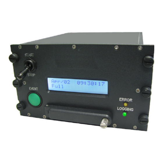
SSR-500s are compact, lightweight, rugged recorders with integrated
data acquisition. The SSR/CHS/001 is an SSR-500 chassis for which a
range of plug-in modules is available, providing interfaces such as A/D
conversion, avionic bus monitoring, and video compression. Built-in
inputs include audio and IRIG-B/GPS. A rear panel Ethernet port is
provided for setup and real-time monitoring. Control is via a START/STOP
switch and an EVENT button, via external start/stop and event inputs
through the I/O connector, or SNMP commands through the Ethernet link.
Data is stored on a removable CompactFlash memory card, currently with
capacities of up to 128 GB industrial grade. A PC identifies such
removable storage as a FAT32 drive so files are instantly accessible with
no need for additional conversion software. Files are in the popular PCAP
format and are readable by the GS Works 9 display and analysis package,
as well as other third party software products.
o
C
The front panel is designed to be user-friendly with a clean and simple
layout. The setup software, DAS Studio 3, is streamlined for fast
configuration, with minimal time required before the system is ready to
record.
Figure 1: Block diagram for the SSR/CHS/001
CURTISSWRIGHTDS.COM
SSR/CHS/001/D
1
Advertisement

Subscribe to Our Youtube Channel
Related Manuals for Curtiss-Wright SSR/CHS/001


Summary of Contents for Curtiss-Wright SSR/CHS/001
- Page 1 CURTISSWRIGHTDS.COM Overview SSR-500s are compact, lightweight, rugged recorders with integrated data acquisition. The SSR/CHS/001 is an SSR-500 chassis for which a range of plug-in modules is available, providing interfaces such as A/D conversion, avionic bus monitoring, and video compression. Built-in inputs include audio and IRIG-B/GPS.
-
Page 2: Specifications
5.35 Bias current – – Signal strength -138 – – Antenna gain © 2020 Curtiss-Wright. All rights reserved. Specifications are subject to change without notice. CURTISSWRIGHTDS.COM All trademarks are the property of their respective owners. 24 Nov. 2020 | DST/AE/022... - Page 3 85,00 127,00 Mounting Bracket (6 OFF) Nylon Battery Mount 1/4 Turn Dzus Fastener (6 OFF) LED (2 OFF) 146,00 159,00 9,50 9,50 127,00 Figure 2: SSR/CHS/001 mechanical drawing (mounting brackets must be ordered separately) CURTISSWRIGHTDS.COM 24 Nov. 2020 | DST/AE/022...
- Page 4 SSR/CHS/001 TABLE 3 Electrical specifications PARAMETER MIN. TYP. MAX. UNITS CONDITION/DETAILS Input range 2A max. therefore 36W at 18V supply. Reverse polarity protection – – Current available – 2,400 ±7V – 2,000 Combined load on both supplies must not exceed 15W.
- Page 5 Measured from a power-up of the test chassis, using a Meinberg M600 IEEE 1588 Grandmaster, supplying PTPv1 1 μs – – messages to the SSR/CHS/001 via OnTime T208 switch, 250 ns – – configured in IEEE 1588 transparent mode. TABLE 6...
- Page 6 SSR/CHS/001 TABLE 7 Differential ended audio inputs PARAMETER MIN. TYP. MAX. UNITS CONDITION/DETAILS Input voltage operating range (G = 1) – Primary gain = 1; 0 dB = 489 mV. overvoltage protection – Voltages outside of this range can damage input.
- Page 7 SSR/CHS/001 TABLE 10 Battery-backed real-time clock PARAMETER MIN. TYP. MAX. UNITS CONDITION/DETAILS Drift Determined by the temperature compensated crystal oscillator (TCXO) in controller. – – – – Battery duration – – years Expiry date is labeled on battery mount. TABLE 11...
- Page 8 SSR/CHS/001 TABLE 12 RS-422 outputs (continued) PARAMETER MIN. TYP. MAX. UNITS CONDITION/DETAILS Output voltage operating voltage – Absolute voltage of the operating signal must stay within this range. logic 0 – – = 100Ω. 0- ; LOAD logic 1 –...
- Page 9 Name of the PTPv1 subdomain to use. _ALT2 _ALT3 Interval, in seconds, between sync messages, if the PTPv1 Sync Interval module is operating as a PTPv1 Grandmaster. True Indicates whether the SSR/CHS/001 is a preferred PTPv1 Preferred Grandmaster True False PTP Grandmaster. Settings PTPv2...
- Page 10 SSR/CHS/001 SETUP DATA CHOICE DEFAULT NOTES Interval, in seconds, between announce messages, if PTPv2 Announce Interval the module is operating as a PTPv2 Grandmaster Interval, in seconds, between sync messages, if the PTPv2 Sync Interval module is operating as a PTPv2 Grandmaster.
- Page 11 SSR/CHS/001 SETUP DATA CHOICE DEFAULT NOTES Voltage level on the input which corresponds to Bright Mode 100% brightness of the LCD. Voltage level on the input which corresponds to 0% Dim Mode brightness of the LCD. Settings Defines event packets or periodic status event pack- Event Settings ets.
- Page 12 False False mented into smaller packages. Processes Specify streams which will be blocked from being sent from the SSR/CHS/001, although they will still Filtering(16:1) be recorded. Note that only streams addressed to multicast addresses can be filtered. Settings Ethernet Output Filter. Operates on multicast packets Filtering specified by stream ID.
- Page 13 SSR/CHS/001 SETUP DATA CHOICE DEFAULT NOTES Controller Only Slot 1 Selects which modules the packetizer package will Packetization Sink Slot 2 be sent to for transmission or storage. Slot 3 Slot 4 IRIG-B-In The IRIG-B time source input. IRIG-B Input RecorderStatus The status of the recorder.
-
Page 14: Register Definition
SSR/CHS/001 NAME/DESCRIPTION BASE UNIT DATA FORMAT BITS REGISTER DEFINITION R[15:0] R(15) Event - Event occurred since last read. R(14) Time Jump - This value is asserted when the time has been adjusted by a jump. R(13) Reserved - Reserved for future use. - Page 15 SSR/CHS/001 NAME/DESCRIPTION BASE UNIT DATA FORMAT BITS REGISTER DEFINITION R[15:0] StatusEventNumber R[15:12] Reserved - Reserved for future use. BitVector BitVector Recorder Event Number status. R[11:0] EventNumber - Current recorder event num- ber, binary encoded decimal, 000-999. Filtering(16:1) Parameters Fixed-Word(1023:0) Parameters...
- Page 16 SSR/CHS/001 NAME/DESCRIPTION BASE UNIT DATA FORMAT BITS REGISTER DEFINITION R[47:32] LongitudeHi Unitless R[47:44] Reserved Degrees of Longitude. R[43:32] Degrees - Degrees of longitude 0 to 179. R[31:16] LongitudeLo R[31:24] Minutes - Minutes of longitude 0 to 59. Minutes and decimal minutes of...
- Page 17 Front panel status LEDs Two LEDs are located on the front panel of the SSR/CHS/001. The ERROR LED lights yellow when recording is not possible; the LOGGING LED lights green when recording is taking place. For monitoring purposes, the REC_STATUS pin on the rear- mounted I/O connector signals the status of the ERROR LED.
-
Page 18: Front Panel Display
Figure 5: Wide viewing angle When the SSR/CHS/001 is installed but is not recording data, the data rate seen by the recorder is shown on the bottom right of the display as a percentage of the 40 Mbps nominal logging speed (see the following figure). For example, if the recorder is receiving 30 Mbps, including data from modules and data from Ethernet, the display shows 75%. - Page 19 SNMP Once installed the SSR/CHS/001 is configured using DAS Studio 3 via the Ethernet port. DAS Studio 3 uses SNMP to edit the configuration of the SSR/CHS/001. These settings include: •...
- Page 20 100% brightness brightnessDimMode brightnessBrightMode KAD/ADC/005 family of modules The SSR/CHS/001 does not support programming of modules in the KAD/ADC/005 family, for example the KAD/ADC/006, KAD/ADC/009, KAD/CDC/001 and KAD/LDC/001. For a list of all KAD/ADC/005 family modules, contact Curtiss-Wright support (acra-support@curtisswright.com). CURTISSWRIGHTDS.COM...
- Page 21 SSR/CHS/001 Connector pinout for the SSR/CHS/001 Power Ethernet Voice Figure 7: Connector placement Connector pinout of the Ethernet interface (CON/168/10M NAME SEE SPECIFICATIONS TABLE COMMENT Ethernet interface Ethernet interface Ethernet interface Do not connect Do not connect Ethernet interface Do not connect...
- Page 22 SSR/CHS/001 Connector pinout of the GPS interface (CON/SMA/001 NAME SEE SPECIFICATIONS TABLE COMMENT Excitation output to active antenna and RF Center RF_IN Onboard GPS receiver input to module Outer shell RF_GND Onboard GPS receiver RF ground reference; isolated from chassis...
- Page 23 The SSR/CHS/001 can be supplied with orange metalized stripes to be attached to the front panel to indicate flight test equipment. Spare lids (ACM/LID/001) for unused user-slots can be supplied. These are optional items and must be ordered separately;...
- Page 24 IENA and iNET-X packet payload formats TEC/NOT/072 Time and leap seconds © 2020 Curtiss-Wright. All rights reserved. Specifications are subject to change without notice. CURTISSWRIGHTDS.COM All trademarks are the property of their respective owners. This document was reviewed on 03/11/2020 and does not contain technical data.
Need help?
Do you have a question about the SSR/CHS/001 and is the answer not in the manual?
Questions and answers