Viking E-35-EWP Product Manual
Voip entry phones with analog color video camera
Hide thumbs
Also See for E-35-EWP:
- Product manual (9 pages) ,
- Technical practice (8 pages) ,
- Application note (2 pages)
Table of Contents
Advertisement
Quick Links
Designed, Manufactured and Supported in the USA
VIKING
SECURITY & COMMUNICATION
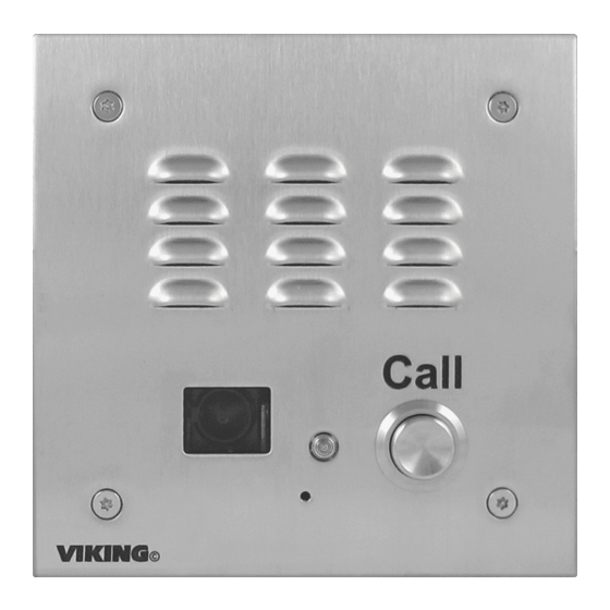
Built-In Analog Color Video Camera
The E-35-IP VoIP Entry Phone is designed to provide quick and reliable
handsfree communication for SIP VoIP phone systems with PoE. The E-
35-IP Entry Phone can be programmed from any Touch Tone phone, PC,
or remotely using a static IP address. The Entry phones can dial up to 5
programmable numbers. On-board 2 Amp relay contacts are provided for
activating doorstrikes or gate controllers. An optional RC-4A Secure Relay
Controller can also be used.The E-35-IP Entry Phone will flash the "Call"
LED during dialing and automatically light the LED when the call is
answered. All programming parameters, including phone numbers and
location numbers, are stored in non-volatile memory, requiring no batteries.
The unit is PoE powered.
The E-35-IP-EWP shares all the features of the E-35-IP in addition to
Enhanced Weather Protection (EWP) for outdoor installations where the
unit is exposed to precipitation or condensation. EWP products are
designed to meet IP66 standards and may feature foam rubber gaskets,
Installation requires the assistance of a Network Administrator / IT Technician.
!
Features
• Built-In high resolution analog NTSC color video camera with wide viewing
angle, tilt/swivel adjustments and wide operating temperature
• Automatic polling and programming software included
• 2 Amp relay contacts for door/gate or SL-2 strobe light control
• Blue "Call" LED indicator
• SIP compliant (see page 2 for compatible SIP servers and IP phone systems)
• Outbound Proxy, Authentication ID, Peer to Peer, VLAN Tagging
• PoE powered (class 1, <4 watts)
• Automatic Noise Canceling (ANC) feature for proper operation in noisy
environments
• VoIP eliminates the need for "Push to Talk" mode
• T-10 Torx security screws for added security
• Can be used with optional RC-4A Secure Relay Controller (DOD 582)
• Handsfree operation
• Marine grade 316 stainless steel prevents corrosion
• Laser Etched graphics on stainless steel models
• Programmable to dial up to 5 numbers on busy or ring no answer
• Cycles through backup phone numbers on busy or no-answer
• Optional Enhanced Weather Protection (EWP), EWP products are
designed to meet IP66 Ingress Protection Rating, see DOD 859
• Hangs up on busy signal, time-out or touch tone command
• Remotely programmable
• Extended temperature range (-40°F to 140°F)
• Replacement board available
• Volume adjustments for microphone and speaker
• E-35-IP is flush mountable using the included rough-in box or can be
surface mounted using an optional VE-5x5 Surface Mount Box (DOD 424)
• Optional PB-100 Polling System available (DOD 232)
• Optional SL-2 or BLK-4-EWP strobe light kit available (DOD 242/653)
• Diagnostics (for testing mic, speaker & relay)
PRODUCT
MANUAL
VoIP Entry Phones with
Analog Color Video Camera
Standard
Flush Mount
sealed connections, gel-filled butt connectors, as well as potted circuit
boards with internally sealed, field-adjustable trim pots and DIP switches
for easy on-site programming. For more information on EWP, see DOD 859.
Applications
• Gate Entrance
• Parking ramps/lots
• ATM machines
• Medical centers
• Lobbies
Specifications
Power: PoE class 1 (<4 watts)
Maximum Sound Pressure: 95 dB SPL @ 1m.
Dimensions: Overall-5" x 5" x 2.25" (127mm x 127mm x 57mm),
Plastic Electrical Box-4" x 4" x 2.12" (102mm x 102mm x 54mm)
Shipping Weight: 2 lbs (0.9 Kg)
Operating Temperature: -40°F to 140°F (-40° C to 60° C)
Humidity - Standard Products: 5% to 95% non-condensing
Humidity - EWP Products: Up to 100%
Audio Codecs: G711u, G711a, G722
Network Compliance: IEEE 802.3 af PoE, SIP 2.0 RFC3261,
100BASE-TX with auto cross over
Regulatory Compliance: FCC Part 15 and Canada ICES-3 Class A
Connections:
(1) RJ45 10/100 Base-T, (6) gel-filled butt
connectors (3M Scotchlok UR2)
(See page 3 for camera specifications)
E-35-IP/EWP
VoIP Entry Phones with
September 28, 2021
Shown in Optional
VE-5x5 Surface Mount Box
• Entryways
• Stadiums
• Convention centers
• Public access areas
Advertisement
Table of Contents

Related Manuals for Viking E-35-EWP


Summary of Contents for Viking E-35-EWP
- Page 1 Designed, Manufactured and Supported in the USA E-35-IP/EWP VIKING PRODUCT VoIP Entry Phones with Analog Color Video Camera MANUAL SECURITY & COMMUNICATION September 28, 2021 VoIP Entry Phones with Built-In Analog Color Video Camera The E-35-IP VoIP Entry Phone is designed to provide quick and reliable handsfree communication for SIP VoIP phone systems with PoE.
- Page 2 VoIP SIP System Compatibility For compatibility and vendor specific detailed configuration instructions, see the Viking VoIP SIP System Compatibility List, DOD 944. To open and download this PDF file: Scan the QR code below to open 1. Go to www.vikingelectronics.com...
-
Page 3: Camera Specifications
Right 30° correct video color in outside applications. The standard camera is NOT compatible with IR illuminators. If IR illumination is required, you will need to replace the existing camera with a Viking model VCAM-1IR. For more information, see DOD# 190. -
Page 4: Features Overview
* Note: The front panel of the E-35-IP is mounted using security Torx screws to help prevent intruders from removing the panel and accessing the on board door strike/gate control relays. For applications requiring additional security, a Viking model RC-4A remote relay controller can be used. -
Page 5: Installation
The E-35-IP is designed to be flush mounted to the included 4” x 4” x 2” deep plastic rough in box or surface mounted using an optional Viking model VE-5x5. Important: The E-35-IP will NOT mount to a standard double gang box. The plastic rough in box (part # 259576) may be purchased separately. - Page 6 B. Replacement IP Board Kit (Model E-1600-53A-IP) This is a board (PCB) only kit, no chassis is included. This kit can be used to convert any Viking E-35 analog phone to a VoIP version. The kit can also be used to replace a damaged IP board in the field. This kit comes in standard and EWP version.
- Page 7 *** Note: RG59 or RG6 with solid center conductor and 95% bare copper braid shield. *** Note: For ease of installation, a Viking Female "F" to Wire Converter Cable can be used (Part # 261217) or "BNC" to wire converter cable (Part # U213510) can be used.
-
Page 8: Adjusting The Camera
RL 2 RL 3 RL 4 NETWORK supplies Responsibility (Extends range of Optional Viking model cable, keeps 1 Gbps RC-4A Secure Remote network speed for other Relay Controller, see equipment on network) page 8 (DOD# 582) * Note: A PoE extender can be used for an additional 100 meters per extender. For longer runs (up to 2 km / 1.2 miles) a ethernet to fiber media converter can be used. -
Page 9: Connect / Disconnect
5. Follow the prompts on your screen to complete software installation 6. To start the Viking IP Programming application, click on the Viking IP Programming icon on your desk top. The Main screen will appear, allowing the user to program any E-35-IP connected to that LAN. - Page 10 C. Configuring the E-35-IP Network Settings Open the “Viking IP Programming” software on a windows PC that is connected to the same LAN as the E-35-IP phone Step 1. to be programmed. The window in the upper left corner of the menu will show you each E-35-IP phone that is connected to that LAN.
- Page 11 D. Configuring E-35-IP VLAN Settings Step 1. Click on the “VLAN” tab Step 2. Disable or enable VLAN tagging by setting the value of “VLAN Tagging”. Step 3. Set the VLAN tag ID by selecting an integer (1 to 4094) in “ID for all packets”. Set the Priority Code Point (PCP) value for all not SIP and RTP packets in the “PCP for all packets”...
- Page 12 Programming Features Index DESCRIPTION Section Page Connect/Disconnect VLAN Settings Unit Name SIP Server Peer to Peer Settings Outbound Proxy Authentication ID Register Fails Speed Dial Numbers Security code (factory set to 845464) ID Number Access Code (1 - 6 digits, blank = disabled, factory set to 123456) Internal / External Relay (factory set to Internal) Relay Mode (Door Strike, Outbound Call, In / Outbound Call, Doorbell, LV-1K Control, Ring, Ring Flash, factory set to Door Strike) Relay Activation Command (1 or 2 digits, factory set to...
-
Page 13: Programming Features
Programming Features 1. Unit Name Up to a 31 character unit name can be assigned to the E-35-IP being programmed. 2. SIP Server Enter the IP address or URL of your SIP server or service provider in this field. The SIP server IP address is limited to 74 characters. -
Page 14: Security Code
Note: A majority of the features below can also be Touch Tone (In-Band DTMF) programmed. See DOD 949. 7. Speed Dial Phone Numbers Note: Up to 79 digits can be stored in each of the 5 speed dial phone number positions. The number programmed in the first location under “Speed Dial Numbers”... - Page 15 With the relay set to “Internal” the E-35-IP will activate its on board relay for door strike / gate control. The Relay should be set to “External” for higher security installations when using a Viking remote model RC-4A relay controller to activate the door strike / gate controller (see page 22).
- Page 16 16. Relay Latch Commands When set to “Enabled” the Remote Access Operation Commands (Q0 to Q1) to Un-Latch or Latch the relay are enabled. These can be entered on a Inbound call after the access code is dialed (if programmed). When set to “Disabled”...
-
Page 17: Lap Counter
25. Lap Counter With the lap counter disabled, if the E-35-IP is programmed to dial the next number on ring-no-answer and/or busy signal, the E-35-IP will continuously call its programmed phone numbers forever until the call is answered. The lap counter is a programmable counter that determines how many times the E-35-IP will cycle through its list of up to 5 Speed Dial phone numbers, before it stops the dialing process and hangs up. - Page 18 29. Dial Next Number on Ring No Answer If enabled and a ring-no-answer is detected, the E-35-IP will dial the next programmed Speed Dial number after the programmed amount of rings. A momentary press of the call button will dial the first programmed Speed Dial number. Factory Setting: 7 (will dial after 7 rings) 30.
- Page 19 An alternative method of updating can be done by clicking the IP firmware “Update IP” button. You can then browse to the folder that contains the PIP file for updating the unit’s IP firmware. This method is typically only used when Viking Technical Support has sent you updated IP firmware 37. Unit Firmware If new E-35-IP firmware is available, after opening the programming software a pop up window will ask if you would like to update firmware.
- Page 20 Group settings and Addresses. Note: This will not effect any speaker or paging settings. 41. Diagnostics The Diagnostics section in the Viking IP Programming can be used to test the functionality of the mic, speaker and the on-board relay. Note: This will not work when relay mode is set to external or Alarm.
-
Page 21: Operation
You may silence the error beeps, per instance, by pressing and holding the CALL button for 5 seconds or by clicking the “Mute Alarm Until Next Failure” button in the Viking IP Programming Software (see section B on page 10). The error beeps... - Page 22 RC-4A to activate its relays which control the door strikes/gates. Up to 4 Viking VoIP Entry Phones can communicate with one RC-4A allowing you to securely control four entrances. When using an RC-4A for remote relay control the relays should be set to “External” in the PC programming.
-
Page 23: Related Products
Caution: Handsfree phones are not suitable for noisy applications (see “Important” on page 2). For more information on Viking Surface Mount Boxes and Pedestals, see DOD 424. Add Panel Lighting to Your Viking VoIP Entry Phone The VE-LIGHT kit adds bright LED illumination to any VoIP entry phone that is housed in a Viking VE-5x5, VE-6x7 or VE-5x10 enclosure. -
Page 24: Warranty
TWO YEAR LIMITED WARRANTY Viking warrants its products to be free from defects in the workmanship or materials, under normal use and service, for a period of two years from the date of purchase from any authorized Viking distributor. If at any time during the warranty period, the product is deemed defective or malfunctions, return the product to Viking Electronics, Inc., 1531 Industrial Street, Hudson, WI., 54016.
Need help?
Do you have a question about the E-35-EWP and is the answer not in the manual?
Questions and answers