Table of Contents

Related Manuals for Albalá Ingenieros ASW3000C01


Summary of Contents for Albalá Ingenieros ASW3000C01
- Page 1 ASW3000C01 DVB-ASI AUTOMATIC CHANGE-OVER SWITCH WITH ADVANCED TS FAILURE DETECTION FUNCTIONS Version 1.0 Albalá Ingenieros, S.A. 17 November 2014 - © Albalá Ingenieros S.A. - All rights reserved Medea, 4 - 28037 Madrid - Spain...
- Page 2 ASW3000C01...
-
Page 3: Table Of Contents
ASW3000C01 DVB-ASI AUTOMATIC CHANGE-OVER SWITCH WITH ADVANCED TS FAILURE DETECTION FUNCTIONS Version 1.0 1. DESCRIPTION ........................5 1.1. The ASW3000C01 .......................... 5 1.2. Features ............................. 7 1.3. Block diagram ..........................8 2. SPECIFICATIONS ......................... 9 3. INSTALLATION ........................11 3.1. Initial inspection .......................... 11 3.2. - Page 4 4.4.6. Signal at the output when errors are present at the inputs ........ 23 4.4.7. Selection of DVB-T/no DVB-T mode ................23 4.5. Module remote control and supervision ................24 4.5.1. Details of the ASW3000C01 registers ................. 25 5. GLOSSARY ........................29 6. REGULATIONS ........................31...
-
Page 5: Description
ASW3000C01 1. DESCRIPTION 1.1. The ASW3000C01 The ASW3000C01 automated switch is a selector for two sources of DVB-ASI signals that operates based upon the presence of signals, specific parameters of those signals or the activation of GPI signals. The ASW3000C01 provides two signal inputs, Main and Reserve. The selected input is... - Page 6 SNMP management and the ability to record events in a file including date and time information for further analysis. The ASW3000C01 is a TL3000 terminal line module and can be housed in a three rack unit (3 RU) UR3000 mounting frame or a 1 RU UR3100 mounting frame.
-
Page 7: Features
• Module control and supervision can be done remotely when the mounting frame is equipped with a communications controller module. • One UR3000 mounting frame can house up to 12 ASW3000C01 modules. If power supply redundancy is required and FA3000 or FA3001 modules are used then only 10 modules can be housed in the mounting frame. -
Page 8: Block Diagram
Albalá Ingenieros | Manual ASW3000C01 1.3. Block diagram... -
Page 9: Specifications
Albalá Ingenieros | Manual ASW3000C01 2. SPECIFICATIONS DVB-ASI signal input Connector Impedance 75 Ω ± 1 % Return loss >17 dB up to 270 MHz Input return loss when bypass is active >17 dB up to 270 MHz Output protected with bypass relay... - Page 10 Albalá Ingenieros | Manual ASW3000C01 ASW3000C01...
-
Page 11: Installation
ELECTROSTATIC DISCHARGE. Always use antistatic bags clearly identified with a high degree of shielding for storage and transportation. The ASW3000C01 module is composed of two parts: one ASW3000P01 main board and one ASW3000P02 rear board. Both parts must be installed in a UR3000 or UR3100 mounting frame following the instructions in the corresponding section of this chapter. -
Page 12: Environmental Considerations
3.5. Installing the module in the mounting frame The steps needed to install the ASW3000C01 module with the rear board in the mounting frame are: 1 - Disconnect all power cords from the power supplies of the mounting frame. - Page 13 Albalá Ingenieros | Manual ASW3000C01 Details for installation of the module in 3 RU mounting frames Details for installation of the module in 1 RU mounting frames...
-
Page 14: Interconnection
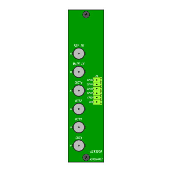
The following figure shows the ASW3000C01 module rear board connector layout. Rear view of the ASW3000C01 The ASW3000C01 module provides two DVB-ASI digital video inputs (MAIN IN and RSV IN) and four DVB-ASI digital video outputs (OUT1p, OUT2, OUT3 and OUT4). It also provides five GPIO inputs/outputs, (GPIO1 to GPIO5). -
Page 15: Electrical Dvb-Asi Video Connections
All coaxial cable used must be Belden 8281 or similar. This type provides the greatest lengths because it is used to calculate the equalizers in the ASW3000C01. Cables carrying signal between the module and the devices should use single piece construction, avoiding spliced sections with double BNC female or barrel connectors. - Page 16 Albalá Ingenieros | Manual ASW3000C01 The lines indicated as GPIO n the silkscreening are assigned as follows: GPIO5: Error input for the reserve channel. GPIO4: Error input for the main channel. GPIO3: Alarm output for the reserve channel. GPIO2: Alarm output for the main channel.
-
Page 17: Operation
Albalá Ingenieros | Manual ASW3000C01 4. OPERATION This section describes the significance of the front panel indicators of the ASW3000C01 module and their remote control and monitoring ability. 4.1. Front panel description The appearance of the front panel and the elements it contains are shown in the following illustration. -
Page 18: Configuration From The Front Panel
SWITCH MODE box. In manual mode, quick presses of the button change the selected input. 4.3. Functional description The ASW3000C01 contains two man functional blocks: one that detects errors in the DVB-ASI inputs and the other with the control logic used to determine which output to use. -
Page 19: The Error Conditions
The control and basic supervision of the ASW3000C01 can be done from the front panel. The pushbutton and LEDs can be used to change the operating mode, select the input and rearm the switching alarm condition. -
Page 20: Error In The Sync Byte Of The Packets
Albalá Ingenieros | Manual ASW3000C01 This condition corresponds to 1.1 TS_sync_loss as per ETSI TR 101 290 V1.2.1 (2001-05). Once synchronization with the stream is established an analysis of the other parameters becomes possible. If the presence of a sync signal is not detected and a lock to that signal is not achieved then none of the other parameter analyzed are valid. -
Page 21: Useful Load Of The Transport Stream
In this operating mode a series of priorities are established and at any given moment the ASW3000C01 selects the highest priority input that does not have any error conditions. The input priority is configurable and can set the Main input to the highest priority and the Reserve input to the lowest priority, or the inverse can be programmed. -
Page 22: Semiautomatic Mode Operation
For software versions v1.2 and above: the number of switching events is minimized. No priorities are established for the inputs, and the ASW3000C01 only switches if an error is detected in one input and the other input is error-free. If both inputs are error-free then the input selected can be changed with a sustained press lasting longer than one second of the RESET button. -
Page 23: Signal At The Output When Errors Are Present At The Inputs
4.4.6. Signal at the output when errors are present at the inputs For software versions v1.5 and above the behavior of the outputs of the ASW3000C01 can be selected when both inputs have a severe error (no signal present or stream sync is not detected): the output can either be cut off or the data received at the selected input can be passed through. -
Page 24: Module Remote Control And Supervision
Albalá Ingenieros | Manual ASW3000C01 4.5. Module remote control and supervision The ASW3000C01 can optionally be remotely controlled/supervised. In order to perform remote configuration and supervision of the module an optional TL3000 family remote communications controller must be installed in the mounting frame. -
Page 25: Details Of The Asw3000C01 Registers
- Status supervision for the input signals. 4.5.1. Details of the ASW3000C01 registers The ASW3000C01 module provides control and status registers that can be read and written by means of specific commands described in the communication control module user manuals. - Page 26 Albalá Ingenieros | Manual ASW3000C01 INVERT_GPI3_POL 0x03 0x04 Changes GPI3 polarity to normally closed 0=No, 1=Yes INVERT_GPI4_POL 0x03 0x08 Changes GPI4 polarity to normally closed 0=No, 1=Yes INVERT_GPI5_POL 0x03 0x10 Changes GPI5 polarity to normally closed 0=No, 1=Yes BITRATE_MIN 0x04...
- Page 27 Albalá Ingenieros | Manual ASW3000C01 RES_PAT_CC_FAIL 0x03 0x20 Main PAT continuity counter status 0=OK,1=Fail RES_TRAFF_FAIL 0x03 0x40 Main bitrate status 0=OK,1=Fail RES_NULL_P_FAIL 0x03 0x80 Main null packet rate status 0=OK,1=Fail MAIN_BITRATE 0x04 0xFFFF Main bitrate = 2*x kbit/s RES_BITRATE 0x06...
- Page 28 Albalá Ingenieros | Manual ASW3000C01 ASW3000C01...
-
Page 29: Glossary
Albalá Ingenieros | Manual ASW3000C01 5. GLOSSARY Cyclic Redundancy Check. Coding used to confirm the bitstream integrity. For 3G/HD-SDI signals each line of video includes coding for confirmation that the line content is correct. DVB-ASI Asynchronous Serial Interface. An asynchronous serial interface for DVB streams that is one of the principal formats for transmission of MPEG-2 streams over cable. - Page 30 Albalá Ingenieros | Manual ASW3000C01 ASW3000C01...
-
Page 31: Regulations
Albalá Ingenieros | Manual ASW3000C01 6. REGULATIONS EN 50083-9 (1998) Interfaces for CATV/SMATV headends and similar professional equipment for DVB/MPEG-2 transport streams. ETSI TR 101 290 V1.2.1 (2001) Digital Video Broadcasting (DVB); Measurement guidelines for DVB systems. - Page 32 Albalá Ingenieros | Manual ASW3000C01 ASW3000C01...
-
Page 33: Versions
Albalá Ingenieros | Manual ASW3000C01 7. VERSIONS Ver. Date Description 13-06-2013 Preliminary Version 17-11-2014 First version... - Page 34 Albalá Ingenieros, S.A. Medea, 4 - 28037 Madrid Spain +34 913274453 www.albalaing.com info@albalaing.com...
Need help?
Do you have a question about the ASW3000C01 and is the answer not in the manual?
Questions and answers