Table of Contents
Advertisement
Quick Links
Advertisement
Table of Contents

Related Manuals for Albalá Ingenieros IPA3000C01


Summary of Contents for Albalá Ingenieros IPA3000C01
- Page 1 IPA3000C01 DVB-ASI AND DVB-IP AUTOMATIC CHANGE-OVER SWITCH WITH TS FAILURE DETECTION FUNCTIONS AND SEAMLESS SWITCHING Version 1.0 Albalá Ingenieros, S.A. 18 August 2015 - © Albalá Ingenieros S.A. - All rights reserved Medea, 4 - 28037 Madrid - Spain...
- Page 2 IPA3000C01...
-
Page 3: Table Of Contents
4.5. System latencies .......................... 23 4.6. Redundant IP transmitter mode ..................... 26 4.7. Module remote control and supervision ................28 4.7.1. Details of the IPA3000C01 registers ................29 5. GLOSSARY ........................41 6. REGULATIONS ........................43 7. VERSIONS ......................... 45... - Page 4 IPA3000C01...
-
Page 5: Description
1. DESCRIPTION 1.1. The IPA3000C01 The IPA3000C01 module is an automatic DVB-ASI and DVB over IP switch that performs switching based upon presence of signal at the inputs, reception of frame synchronization and information received via the GPI connector as per the priorities assigned by the user to each input. - Page 6 SNMP management and the ability to record events in a file including date and time information for further analysis. The IPA3000C01 is a TL3000 terminal line module and can be housed in a three rack unit (3 RU) UR3000 mounting frame or a 1 RU UR3100 mounting frame.
-
Page 7: Features
• Module control and supervision can be done remotely when the mounting frame is equipped with a communications controller module. • One UR3000 mounting frame can house up to 12 IPA3000C01 modules. If power supply redundancy is required and FA3000 or FA3001 modules are used then only 10 modules can be housed in the mounting frame. - Page 8 Albalá Ingenieros | Manual IPA3000C01 • One UR3100 mounting frame can house up to three IPA3000C01 modules. • Low power.
-
Page 9: Block Diagram
Albalá Ingenieros | Manual IPA3000C01 1.3. Block diagram... - Page 10 Albalá Ingenieros | Manual IPA3000C01 IPA3000C01...
-
Page 11: Specifications
Albalá Ingenieros | Manual IPA3000C01 2. SPECIFICATIONS DVB-ASI signal input Connector Impedance 75 Ω ± 1 % Return loss >17 dB up to 270 MHz Input return loss when bypass is active >17 dB up to 270 MHz Output protected with bypass relay... - Page 12 Albalá Ingenieros | Manual IPA3000C01 Allowed voltage range 1PPS reference signal input Connector Impedance 50 Ω ± 1 % Threshold levels: min. 2.0 V max. 0.8 V GPI input Connector Plug-in terminal, 3.81 mm pitch Type 10 kΩ pull-up to 5 V...
-
Page 13: Installation
ELECTROSTATIC DISCHARGE. Always use antistatic bags clearly identified with a high degree of shielding for storage and transportation. The IPA3000C01 module is composed of two parts: one IPA3000P01 main board and one IPA3000P02 rear board. Both parts must be installed in a UR3000 or UR3100 mounting frame following the instructions in the corresponding section of this chapter. -
Page 14: Environmental Considerations
4 - Attach the rear board to the mounting frame with two M3 metric screws and tighten. 5 - Insert the IPA3000P01 board (main board of the IPA3000C01 module) into the front of the mounting frame. The edges of the card slide into two plastic guides inside the mounting frame. - Page 15 Albalá Ingenieros | Manual IPA3000C01 Details for installation of the module in 3 RU mounting frames Details for installation of the module in 1 RU mounting frames...
-
Page 16: Interconnection
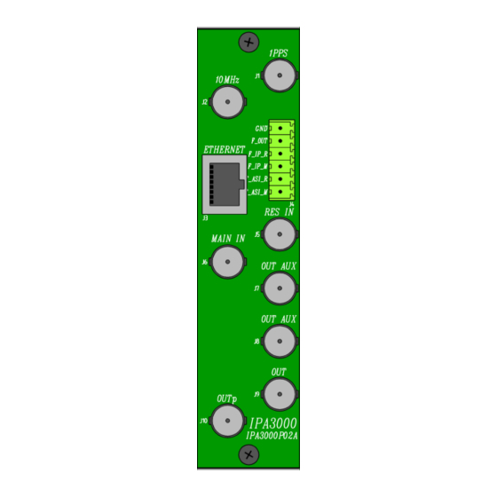
The following figure shows the IPA3000C01 module rear board connector layout. Rear view of the IPA3000C01 The IPA3000C01 module includes two inputs (MAIN IN and RES IN) and four DVB-ASI signal outputs (OUT AUX, OUT AUX, OUT and OUTp). The OUTp connector corresponds to the output that is protected with a bypass relay such that signal integrity is maintained in case of a power supply failure or extraction of the module from the mounting frame. -
Page 17: Electrical Dvb-Asi Video Connections
All coaxial cable used must be Belden 8281 or similar. This type provides the greatest lengths because it is used to calculate the equalizers in the IPA3000C01. Cables carrying signal between the module and the devices should use single piece construction, avoiding spliced sections with double BNC female or barrel connectors. -
Page 18: Gpi Connections
Albalá Ingenieros | Manual IPA3000C01 3.6.2. GPI connections The GPI inputs use 3.81 mm pitch terminal block connectors and their equivalent circuit is as follows: Before connecting these signals please consult the maximum values shown in the specifications section. Never connect dangerous potentials to GPI inputs. -
Page 19: Operation
Albalá Ingenieros | Manual IPA3000C01 4. OPERATION This section describes the significance of the front panel indicators of the IPA3000C01 module and their remote control and monitoring ability. 4.1. Front panel description The appearance of the front panel and the elements it contains are shown in the following illustration. - Page 20 Albalá Ingenieros | Manual IPA3000C01 In the INPUT FAIL box: ASI MAIN, ASI RES, IP MAIN, IP RES: Red. These LEDs light up to indicate errors for the corresponding input. They light up continuously when no signal is present, when the frame...
-
Page 21: Configuration From The Front Panel
DVB-T mode) is invalid or when the corresponding GPI for the given input is connected to ground. When an error at the input is produced the IPA3000C01 will only switch to a lower priority input when that input is error-free. -
Page 22: Operation In Semi-Automatic Mode
Albalá Ingenieros | Manual IPA3000C01 forces the IPA3000C01 to wait for a given period of time after an input error is cleared before switching to that input. The default recovery time is two seconds. When the IPA3000C01 is operating in a mode other than Generic DVB and with seamless switching a recovery time greater than two seconds may be needed due to the longer periods needed to align the transport streams in non-DVB-T modes. -
Page 23: Description Of The Ts Over Ip Encapsulators/De-Encapsulators
RTP protocol a single frame (FEC Type A) or two frames (FEC Type B) of auxiliary data can be sent in order to correct errors or dropped packets. When using the RTP protocol the IPA3000C01 can be configured to substitute dropped and non-recoverable packets of the TS with null packets. - Page 24 50 ms greater than the TS input delays received. This difference is due to the response time of the frame synchronization error detectors. When the IPA3000C01 operates in this mode the delay fields in the "General" tab of the control software display the delay of the transport streams received with respect to the 1 PPS reference signal.
- Page 25 Albalá Ingenieros | Manual IPA3000C01 An additional reason that a small buffer size is recommended when the IPA3000C01 operates in this mode is that buffer size affects the recovery time before seamless switching can be performed. The larger the buffer size the longer the seamless switching recovery time.
-
Page 26: Redundant Ip Transmitter Mode
4.6. Redundant IP transmitter mode Two IPA3000C01 modules can be configured with the same IP parameters so that they deliver one multicast IP stream with redundancy that cannot be duplicated at any time. This is done by correctly interconnecting the GPIO's of the two modules so that each module signals its status to the other while monitoring the other's status. - Page 27 Albalá Ingenieros | Manual IPA3000C01 It's important to configure the output activation delay of the main module to ensure that it does not transmit simultaneously with the reserve module when the signal is recovered. If this is not done, the main module will begin to transmit the IP stream at the same time that it activates its GPO signaling to the reserve module that it should stop transmitting.
-
Page 28: Module Remote Control And Supervision
Albalá Ingenieros | Manual IPA3000C01 4.7. Module remote control and supervision The IPA3000C01 requires remote control for configuration. In order to perform remote configuration and supervision of the module an optional TL3000 family remote communications controller must be installed in the mounting frame. -
Page 29: Details Of The Ipa3000C01 Registers
- Supervision of the status of the inputs and outputs. 4.7.1. Details of the IPA3000C01 registers The IPA3000C01 module provides control and status registers that can be read and written by means of specific commands described in the communication control module user manuals. - Page 30 Albalá Ingenieros | Manual IPA3000C01 INPUT_CHANGE 0x02 0x08 Signals a change in selected input 0=No, 1=Yes ENA_ASI_MAIN 0x02 0x10 Allows disabling ASI main input when it is not used 0=Disabled, 1=Enabled ENA_ASI_RES 0x02 0x20 Allows disabling ASI reserve input when it is not used...
- Page 31 Albalá Ingenieros | Manual IPA3000C01 INVERT_GPO_POL 0x00 0x33 0x02 Changes output polarity to normally closed 0=No, 1=Yes INP_FAIL_MODE 0x00 0x34 0x01 Selects if the output is muted when all the inputs fail 0=Yes, 1=No 188_BYTE_MODE 0x00 0x36 0x01 Allows trimming packets at the input to 188 bytes...
- Page 32 Albalá Ingenieros | Manual IPA3000C01 TX_UNI_ENA 0x00 0x58 0x01 Enable TX 0=No, 1=Yes TX_MULTI_ENA 0x00 0x58 0x02 TX mode 0=Unicast, 1=Multicast LOCAL_IP_ADD_3 0x00 0x59 0xFF Unicast IP address (3) LOCAL_IP_ADD_2 0x00 0x5A 0xFF Unicast IP address (2) LOCAL_IP_ADD_1 0x00 0x5B...
- Page 33 Albalá Ingenieros | Manual IPA3000C01 TX_COL_DELAY 0x00 0x77 0xFF FEC column delay LOW_COST 0x00 0x88 0x02 TOS. Low cost 0=No, 1=Yes HIGH_RELIABILTY 0x00 0x88 0x04 TOS. High reliability 0=No, 1=Yes HIGH_THROUGHPUT 0x00 0x88 0x08 TOS. High Throughput 0=No, 1=Yes LOW_DELAY...
- Page 34 Albalá Ingenieros | Manual IPA3000C01 ASIR_IPM_SEAM 0x03 0x08 ASI reserve to IP main seamles switching capability 0=Seamless, 1=No seamless ASIR_IPR_SEAM 0x03 0x10 ASI reserve to IP reserve seamles switching capability 0=Seamless, 1=No seamless IPM_IPR_SEAM 0x03 0x20 IP main to IP reserve seamles switching capability...
- Page 35 Albalá Ingenieros | Manual IPA3000C01 ASI_RES_BUF_UND 0x1D 0x20 ASI reserve buffer underflow 0=OK,1=Fail IP_MAIN_BUF_UND 0x1D 0x40 IP main buffer underflow 0=OK,1=Fail IP_RES_BUF_UND 0x1D 0x80 IP reserve buffer underflow 0=OK,1=Fail BUFFER_STATUS 0x1E 0x7F Buffer filling status in non DVB-T mode = x %...
- Page 36 Albalá Ingenieros | Manual IPA3000C01 ASI_RES_PRIOR 0x07 0x0C Allows selecting the ASI reserve input priority IP_MAIN_PRIOR 0x07 0x30 Allows selecting the IP main input priority IP_RES_PRIOR 0x07 0xC0 Allows selecting the IP reserve input priority STAT_RESET 0x08 0x01 Allows reseting the statistics measurements...
- Page 37 Albalá Ingenieros | Manual IPA3000C01 STR1_MULTIC_ENA 0x00 0x42 0x02 RX mode (IP main RX) 0=Unicast, 1=Multicast TEI_FLAG_EN 0x00 0x42 0x04 Enables Transport Error Indcator Flag in generated NULL packets 0=No, 1=Yes VLAN_RX1_ENABLE 0x00 0x44 0x01 VLAN Enable (IP main RX)
- Page 38 Albalá Ingenieros | Manual IPA3000C01 TX_UIP_ADD_2 0x00 0x66 0xFF Destination IP address (2) TX_UIP_ADD_1 0x00 0x67 0xFF Destination IP address (1) TX_UIP_ADD_0 0x00 0x68 0xFF Destination IP address (0) TX_MIP_ADD_3 0x00 0x69 0xFF Multicast dest. IP address (3) TX_MIP_ADD_2 0x00...
- Page 39 Albalá Ingenieros | Manual IPA3000C01 STR2_IGM_F_ADD_0 0x00 0xA7 0xFF Source IP address (0) (IP reserve RX) STATUS Name snmp trap Description 1PPS_FAIL 0x01 0x01 1PPS reference input status 0=OK,1=Fail 10MHZ_FAIL 0x01 0x02 10MHz reference input status 0=OK,1=Fail OUTPUT_FAIL 0x01 0x08...
- Page 40 Albalá Ingenieros | Manual IPA3000C01 IP_RX_PORT 0x0C 0xFFFF RX packets UDP source port L_PARAM 0x0E 0x1F L parameter (FEC mode columns) FEC_MODE 0x0E 0x60 Protocol 0=UDP, 1=RTP no FEC, 2=RTP FEC A (col.), 3=RTP FEC B (row&col.) PACKET_SIZE 0x0E 0x80...
-
Page 41: Glossary
Albalá Ingenieros | Manual IPA3000C01 5. GLOSSARY 1 PPS One Pulse Per Second. Synchronization signal that consists of one short pulse that is repeated every second. Typically uses TTL levels. Asynchronous Serial Interface. Transmission interface for DVB/MPEG-2 Transport streams as per EN 50083-9. - Page 42 Albalá Ingenieros | Manual IPA3000C01 Global Positioning System. A telecommunication system formed by an array of satellites that transmit information to the earth's surface. Timing and position can be determined by using GPS along with an appropriate receptor. Internet Protocol. A low-level communications protocol used by the internet.
-
Page 43: Regulations
Albalá Ingenieros | Manual IPA3000C01 6. REGULATIONS EN 50083-9 (1998) Interfaces for CATV/SMATV headends and similar professional equipment for DVB/MPEG-2 transport streams. ETSI TR 101 290 V1.2.1 (2001) Digital Video Broadcasting (DVB); Measurement guidelines for DVB systems. IEEE std 802.3... - Page 44 Albalá Ingenieros | Manual IPA3000C01 IPA3000C01...
-
Page 45: Versions
Albalá Ingenieros | Manual IPA3000C01 7. VERSIONS Ver. Date Description 13-06-2013 Preliminary Version 18-08-2015 First version... - Page 46 Albalá Ingenieros, S.A. Medea, 4 - 28037 Madrid Spain +34 913274453 www.albalaing.com info@albalaing.com...
Need help?
Do you have a question about the IPA3000C01 and is the answer not in the manual?
Questions and answers