Table of Contents
Advertisement
Quick Links
Advertisement
Table of Contents
Troubleshooting

Related Manuals for E.F. Johnson Company 5100 ES Series


Summary of Contents for E.F. Johnson Company 5100 ES Series
- Page 1 5100 ES Series Portable Radio Service Manual UHF / 700 / 800 MHz Project 25 Conventional and Trunked Analog and Digital Conventional ® ® SMARTNET /SmartZone 7.2 VDC 4 Watt (UHF), 2.5 Watt (700 MHz), 3 Watt (800 MHz) Part Number 001-5100-60001...
- Page 3 EFJohnson. All other company and/or product names used in this manual are trademarks and/or registered trademarks of their respective manufacturers. Information in this manual is subject to change without notice. 5100 ES Series Portable Radio Service Manual January 2007...
-
Page 5: Table Of Contents
Belt Clip Installation ............. 2-3 January 2007 5100 ES Series Portable Radio Service Manual i... - Page 6 Back End IC............5-6 ii 5100 ES Series Portable Radio Service Manual...
- Page 7 SEM Module ............. . 5-23 January 2007 5100 ES Series Portable Radio Service Manual iii...
- Page 8 Exploded Views ............. . . 9-44 10 Schematic Diagrams and Component Layouts 10-1 iv 5100 ES Series Portable Radio Service Manual January 2007...
- Page 9 023-5500-180/182/185 Logic Board Schematic (Page 4 of 7) ....10-18 10.18 023-5500-180/182/185 Logic Board Schematic (Page 5 of 7) ....10-19 January 2007 5100 ES Series Portable Radio Service Manual v...
- Page 10 Cable Schematics ........... . 10-45 vi 5100 ES Series Portable Radio Service Manual...
- Page 11 Start Up Failure LED Indications ......... . . 7-1 January 2007 5100 ES Series Portable Radio Service Manual vii...
-
Page 12: Table Page
List of Tables (continued) Table Page viii 5100 ES Series Portable Radio Service Manual January 2007... -
Page 13: General Information
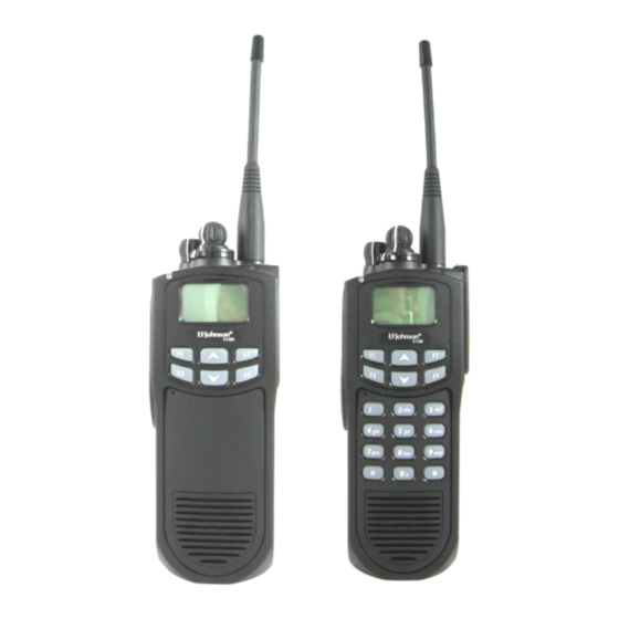
The distinguishing characteristics of the 5100 ES Portable Radio Model I/II/III are shown in Figure 1.1. Figure 1.1 5100 ES Portable Radio Model I/II/III Model I Model II Model III January 2007 5100 ES Series Portable Radio Service Manual 1-1... -
Page 14: Radio Description
Power output is user switchable for low and high levels as follows: UHF - 1 and 4 watts 700 MHz - 1 and 2.5 watts 800 MHz - 1 and 3 watts 1-2 5100 ES Series Portable Radio Service Manual January 2007... -
Page 15: Analog/Digital Operation
512 with the 512 channel option (or the available memory space as described in the following information). The 512-channel option is typically standard with all radios. January 2007 5100 ES Series Portable Radio Service Manual 1-3... -
Page 16: Channels
PC Configure™ programming. All adjustments are made electronically using the software (no manual adjustments are required). For alignment and performance testing information, refer to the PC Tune manual included on the PC Tune 1-4 5100 ES Series Portable Radio Service Manual January 2007... -
Page 17: Part Number Breakdown
7 - I/S Ultra High Capacity - NiMH - Submersible C (Front Housing Color) 0 - Black 1 - Yellow 2 - Orange 3 - Black, Ruggedized Submersible 4 - Yellow, Ruggedized Submersible 5 - Orange, Ruggedized Submersible January 2007 5100 ES Series Portable Radio Service Manual 1-5... -
Page 18: Transceiver Identification
Charger kit, -210 chgr, -230 PS, Eur cord 250-5100-220 Charger kit, -215 chgr, -230 PS, Eur cord 250-5100-225 Charger kit, -235 chgr, Non-Switching Pwr Supply 250-5100-235 4-unit charger kit, -240 station, four -210 250-5100-240 chargers, US cord 1-6 5100 ES Series Portable Radio Service Manual January 2007... -
Page 19: Accessories
585-5100-130 3.0 D-Swivel Belt Loop Only 585-5100-132 Radio D-Swivel button for -130/-132 loops 585-5100-127 Belt Clip, 2 1/2 Standard Spring loaded 585-5100-128 Belt Clip, 3 1/4 Long Spring loaded 585-5100-129 January 2007 5100 ES Series Portable Radio Service Manual 1-7... - Page 20 023-5100-955 Encryption Keyloader Accessories SMA (PDA) keyloader 250-5000-945 SMA keyloader to 5100 radio cable 023-5000-940 SMA keyloader to 5300 radio cable 023-5000-950 KVL 3000 keyloader to 5100 radio cable 585-5000-932 1-8 5100 ES Series Portable Radio Service Manual January 2007...
-
Page 21: Intrinsically Safe Information
• Do not install any accessory that is not specifically approved for use with intrinsically safe 5100 ES models. Approved accessories are indicated by an asterisk (*) in the acces- sories listing in Table 1.1. January 2007 5100 ES Series Portable Radio Service Manual 1-9... -
Page 22: Definitions
• Intermittent making or breaking of a resistive circuit. • Hot-wire fusing. • The following could be sources of thermal ignition: • Heating of a small-gauge wire or PC board trace. • High surface temperature of components. 1-10 5100 ES Series Portable Radio Service Manual January 2007... -
Page 23: Intrinsically Safe And Nonincendive Ratings
Intrinsically Safe - Class I, II, and III, Division 1, Groups C, D, E, F, and G. Nonincendive - Class I, Division 2, Groups A, B, C, and D. Temperature Code - T3C Definitions of these Class, Division, and Group designations are in the following sections. January 2007 5100 ES Series Portable Radio Service Manual 1-11... -
Page 24: Classification Of Hazardous Areas (Division)
Metal dust including aluminum, magnesium, and their alloys Carbon black, coal, or coke dust Flour, starch, or grain dusts Ignitable fibers/flyings such as rayon or cotton 1-12 5100 ES Series Portable Radio Service Manual January 2007... -
Page 25: Secure Communication
Project 25 conventional channels. Future OTAR of AES keys and on Project 25 trunked channels is planned. Note Refer to the 5100 ES Operating Manual for more information on OTAR and on secure communication. January 2007 5100 ES Series Portable Radio Service Manual 1-13... -
Page 26: Typical Performance Specifications
6.7" x 2.52" x 1.9" (6.4 cm x 17.0 cm x 4.8 cm) (HxWxD) Weight (with standard battery) 24 oz. (675 g) Case Polycarbonate–black, yellow, orange Temperature Range -22°F to +140°F (–30°C to +60°C) 1-14 5100 ES Series Portable Radio Service Manual January 2007... - Page 27 -40 dB -40 dB -40 dB 12.5 kHz Channels -35 dB -35 dB -35 dB Audio Distortion All specifications are measured per TIA 102.CAAA, TIA 102.CAAB and per TIA 603 standards. January 2007 5100 ES Series Portable Radio Service Manual 1-15...
- Page 28 (153 x 59 x 22 mm) 700/800 MHz: Minimum 12 hours 7.2 x 2.6 x 2.0 inches (183 0.98 lbs (0.45 kg) (w/12 Alkaline Battery Clamshell 14-16 hours x 67 x 51 mm) AA batt.) 1-16 5100 ES Series Portable Radio Service Manual January 2007...
-
Page 29: Battery, Accessory And Disassembly Information
To remove the battery from the radio for recharging or replacement, press the release button (see Figure 2.1) and then rotate it upward to the approximate point shown and remove it from the radio. Figure 2.1 Battery Removal Battery Release Button January 2007 5100 ES Series Portable Radio Service Manual 2-1... -
Page 30: Battery Charging
A fully charged battery provides approximately 13 hours of service before recharging is required. This time assumes that 5% of the time is spent transmitting, 5% in the receive 2-2 5100 ES Series Portable Radio Service Manual January 2007... -
Page 31: Belt Clip Installation
3 Hold the latch open, press the connector against the transceiver, and then release the latch to lock the connector in place. 4 Install the included locking screw in the latch tab in the location shown. January 2007 5100 ES Series Portable Radio Service Manual 2-3... -
Page 32: Option Select Lines
PTT line (low = PTT), and the radio PTT switch is also functional. The internal speaker and microphone are disabled. Opt Sel 1 High, Opt Sel 2 Low - The encryption keyloader is connected. 2-4 5100 ES Series Portable Radio Service Manual January 2007... -
Page 33: Transceiver Disassembly
Firmly press the chassis and the cover together until they snap in place. January 2007 5100 ES Series Portable Radio Service Manual 2-5... -
Page 34: Removing Rf And Logic Boards From Chassis
8 When handling these boards, minimize bending of the flex circuit to prevent it from being damaged. Before replacing the RF board, make sure there is adequate heat sink compound on the pad under the RF module. 2-6 5100 ES Series Portable Radio Service Manual January 2007... -
Page 35: Removing Ui (User Interface) Board
14 Separate the front cover and chassis as described in Section 2.4.1. Then remove the UI board as described in the preceding section. 15 Pull the rubber knobs and plastic channel number ring off the shafts. January 2007 5100 ES Series Portable Radio Service Manual 2-7... - Page 36 17 Remove the spanner nut on each shaft and slide the switch assembly out of the cover. 2-8 5100 ES Series Portable Radio Service Manual January 2007...
-
Page 37: Operation
The operation of the 5100 ES transceiver is described in the 5100 ES Model I Operating Manual and the 5100 ES Model II/III Operation Manual. These manuals are available from your EFJohnson dealer. January 2007 5100 ES Series Portable Radio Service Manual 3-1... - Page 38 Operation 3-2 5100 ES Series Portable Radio Service Manual January 2007...
-
Page 39: Transceiver Programming
• 5100 Programming Cable, Part No. 023-5100-920 • PC Configure programming software, Part No. 023-9998-527. Figure 4.1 Programming Setup 5100 Programming Cable Connect To Part No. 023-5100-920 Serial Port January 2007 5100 ES Series Portable Radio Service Manual 4-1... -
Page 40: Computer Description
• To upgrade radios to the above firmware versions or later, PC Configure Version 1.24.0 or later must be used. • To upgrade radios to earlier versions than those shown above, PC Configure Version 1.22.0 or earlier must be used. 4-2 5100 ES Series Portable Radio Service Manual January 2007... -
Page 41: Firmware Upgrade Instructions
For example, if the radio currently has Ver 3.1.0, the new code must have a 3.x.x version number, not 2.x.x. or 1.x.x. Code Version Displayed Radio Version Version 1.x.x Standard Version Version 2.x.x SEM Version Version 3.x.x UCM Version January 2007 5100 ES Series Portable Radio Service Manual 4-3... -
Page 42: Pc Configure Upgrade Instructions
6 If new Boot code is also included, copy the “CodeDownLoadROM_1_x.hex” file on the included CD-ROM to the PPC\5100\Upgrade folder under the new version of PC Configure located at C:\Program Files\EF Johnson\PCConfigure. 4-4 5100 ES Series Portable Radio Service Manual January 2007... -
Page 43: Firmware Upgrade Procedure
PTT switch and then turn power on. Release the button and the display will indicate “Bootload Waiting for serial-bus command.” January 2007 5100 ES Series Portable Radio Service Manual 4-5... -
Page 44: Cloning Procedure
With the latest 5100 versions, both wireless and wired cloning are available. For more information on cloning one radio with another, refer to the PC Configure Programming Manual. 4-6 5100 ES Series Portable Radio Service Manual January 2007... -
Page 45: Circuit Description
The DSP processes the received signals and generates the appropriate output signals. The microcontroller controls the hardware and provides an interface between hardware and DSP. 5.1.1.1 PC Boards This radio contains the following PC boards: • RF Board • Logic Board January 2007 5100 ES Series Portable Radio Service Manual 5-1... -
Page 46: Analog Mode
D/A in the CODEC to produce the analog modulation signals for the VCOs. The modulated VCO signal is then sent to the RF power amplifier and transmitted. 5-2 5100 ES Series Portable Radio Service Manual January 2007... -
Page 47: Project 25 Digital Mode
RF PA for transmission. UHF Low RF Board Note The RF Board is not field serviceable. It must be replaced as a unit with a new board. January 2007 5100 ES Series Portable Radio Service Manual 5-3... - Page 48 Circuit Description Figure 5.1 UHF RF Board Block Diagram January 2007 5100 ES Series Portable Radio Service Manual 5-4...
-
Page 49: Receiver
IF Filter and Amplifier A two-pole 64.455 MHz crystal filter (U2) is used to provide the desired level of adjacent channel rejection while providing minimal amplitude and phase distortion within a 25 January 2007 5100 ES Series Portable Radio Service Manual 5-5... -
Page 50: Back End Ic
In receive mode the PLL is programmed for a local oscillator frequency that is 64.455 MHz away from the receive frequency. In transmit mode the PLL is programmed directly for the transmit frequency. 5-6 5100 ES Series Portable Radio Service Manual January 2007... -
Page 51: Reference Oscillator
VSWR conditions. The PA is driven by a SGA-6589 driver (U20) that typically provides +21 dBm output power. The PA is turned on and off by switching the power to this driver via transistor D10. January 2007 5100 ES Series Portable Radio Service Manual 5-7... -
Page 52: Alc
T/R switch are filtered by a harmonic filter that is between the RF T/R switch and the antenna jack. 700/800 MHz RF Board Note The RF Board is not field serviceable. It must be replaced as a unit with a new board. 5-8 5100 ES Series Portable Radio Service Manual January 2007... - Page 53 Circuit Description Figure 5.2 700/800 MHz RF Board Block Diagram January 2007 5100 ES Series Portable Radio Service Manual 5-9...
-
Page 54: Receiver
A LO filter (including W1 and W2) is used prior to LO port of the mixer to reduce the effect of wideband noise from the LO synthesizer on the receiver sensitivity. This filter is varactor-tuned with the center frequency tuned via a voltage from a D/A converter. 5-10 5100 ES Series Portable Radio Service Manual January 2007... -
Page 55: If Filter And Amplifier
IF frequency. The resulting digital words are first filtered by internal programmable FIR filters and then clocked out of the AD9864 via a serial data bus using a programmable data rate. January 2007 5100 ES Series Portable Radio Service Manual 5-11... -
Page 56: Synthesizer
VCO functions for only one of the two receive bands. An RF2361 buffer amplifier (U40) provides the required level of drive for the receiver mixer's local oscillator signal as discussed above. 5-12 5100 ES Series Portable Radio Service Manual January 2007... -
Page 57: Transmitter
Any harmonics generated by the PA module and the RF T/R switch are filtered by a harmonic filter that is between the RF T/R switch and the antenna jack. January 2007 5100 ES Series Portable Radio Service Manual 5-13... -
Page 58: User Interface Board
• 1.8Vdc (SW_VD1_8) –MPC870, FLASH, and CPLD core voltage • 3.3Vdc (SW_VD3_3) – Supply for digital I/O, HC08, and discrete logic devices • 5Vdc (SW_VA5_0) - analog supply • Battery(SW_BATT) – Accessory Connector (J1), speaker audio PAs 5-14 5100 ES Series Portable Radio Service Manual January 2007... -
Page 59: Mpc870 Processor
SRAM is retained when the radio is turned off. A logic gate (U22) disables the SRAM chip select when normal UI Board power is turned off and places the SRAM in a low power consumption state. January 2007 5100 ES Series Portable Radio Service Manual 5-15... -
Page 60: Hpi Bus Multiplexer
The SPI Flash (U40 or U44) is a 512Kbit Flash memory device used to store radio operating parameters. Only one device is present on the board. The device is accessed by the MPC870 via the UI Board SPI bus. 5-16 5100 ES Series Portable Radio Service Manual January 2007... -
Page 61: Audio Out
The single-ended microphone signal is then converted to a differential signal by U19A and U19D to reduce noise. It is then fed to the Logic Board on the AUDIO_IN_P/M lines (J5 - 27 and 25). January 2007 5100 ES Series Portable Radio Service Manual 5-17... - Page 62 Circuit Description Figure 5.3 User Interface Board Block Diagram January 2007 5100 ES Series Portable Radio Service Manual 5-18...
-
Page 63: Logic Board
Transistors Q1 and Q3 control are used to switch on the battery supply to the Logic Board regulators. These transistors are turned on or off by the radio on/off switch or the power hold signal from the MPC870 processor on the UI Board. January 2007 5100 ES Series Portable Radio Service Manual 5-19... -
Page 64: Digital
The Digital Signal Processing (DSP) functions are performed by a TI 5510 DSP (U15) and the TI AIC21 Codec (U27) with the support of MPC870 processor on the UI board. Operation of the DSP is described in the paragraphs below. 5-20 5100 ES Series Portable Radio Service Manual January 2007... -
Page 65: Control Interface
Additionally, the DSP sends data to the Codec via the SSI bus to adjust the TXMOD1 and TXMOD2 signals to set the RF Deck receiver frequency. January 2007 5100 ES Series Portable Radio Service Manual 5-21... -
Page 66: Hpi Bus Multiplexer
MPC870 via the I C control bus. The SSI bus clock (signal CODEC_CLK) is set to 768 KHz with a frame time (signal CODEC_FS) of 24 KHz. 5-22 5100 ES Series Portable Radio Service Manual January 2007... -
Page 67: Sem Module
Operation of the SEM is controlled by the MPC870 on the UI Board through a SPI bus interface on the 5416 DSP. Data to be encrypted or decrypted is passed to the SEM through an SSI bus that is connected to the Logic Board 5510 DSP. January 2007 5100 ES Series Portable Radio Service Manual 5-23... - Page 68 Circuit Description Figure 5.4 Logic Board Block Diagram January 2007 5100 ES Series Portable Radio Service Manual 5-24...
-
Page 69: Alignment Procedure
Performance Tests in the PC Tune manual included on the PC Tune CD. Figure 6.1 Alignment Setup 5100 Test Cable DB9 - Connect To Part No. 023-5100-940 Serial Port Audio In/Out Cable Part No. 023-5100-950 To Communications Analyzer Communications Analyzer January 2007 5100 ES Series Portable Radio Service Manual 6-1... - Page 70 Alignment Procedure 6-2 5100 ES Series Portable Radio Service Manual January 2007...
-
Page 71: Troubleshooting
The PowerPC never received a power up message from the DSP. This error message appears when there is a communication failure between the Cycle Power DSP and the back end ADC on the RF deck. January 2007 5100 ES Series Portable Radio Service Manual 7-1... -
Page 72: User Troubleshooting
The battery should be recharged or replaced as soon as possible after the low battery indications appear. Note If the transceiver contains encryption (hardware) keys, be sure to reattach a battery within approximately one minute to prevent the loss of these keys. 7-2 5100 ES Series Portable Radio Service Manual January 2007... -
Page 73: Additional Information
Please refer to the 5100 ES Model I Operating Manual or the 5100 ES Models II/III Operating Manual for technical information. Contact Information Contact EFJohnson at the numbers and e-mail address shown in Section 8.2. January 2007 5100 ES Series Portable Radio Service Manual 7-3... - Page 74 Troubleshooting 7-4 5100 ES Series Portable Radio Service Manual January 2007...
-
Page 75: Service Information
This information may also be requested from the Warranty Department by phone at the numbers listed in Section 8.2. The Warranty Department may also be contacted for warranty service reports, claim forms, or any other questions concerning warranties or warranty service. January 2007 5100 ES Series Portable Radio Service Manual 8-1... -
Page 76: Factory Customer Service
If local service is not available, the equipment can be returned to the EFJohnson repair depot for repair. However, before returning equipment, contact the Customer Service Department Repair Depot for the correct “Ship To” address. 8-2 5100 ES Series Portable Radio Service Manual January 2007... -
Page 77: Replacement Parts
You may also send your order by mail or fax. The mailing address is as follows and the fax number is shown in Section 8.2. Service Parts Department EFJohnson 1440 Corporate Drive Irving, TX 75038-2401 January 2007 5100 ES Series Portable Radio Service Manual 8-3... -
Page 78: Internet Home Page
EFJohnson has a site on the World Wide Web that can be accessed for information on the company about such things as products, systems, and regulations. The address is http://www.efjohnson.com 8-4 5100 ES Series Portable Radio Service Manual January 2007... -
Page 79: Parts List
E C T I O N Parts List Chapter 9 Parts This section lists the 5100 ES Model I/II/III Portable Radio component descriptions, reference designators (Ref No.), and part numbers (Part No.). January 2007 5100 ES Series Portable Radio Service Manual 9-1... - Page 80 Assembly Controls 023-5100-045 EP 101 TOP SWITCH SEAL 574-3500-071 EP 102 TOP SWITCH SEAL 574-3500-071 MP 040 SWITCH HOLDER NGP 5100 032-0431-171 PC 040 FLEX CKT, CONTROLS (REV 1) 355-1000-4501 9-2 5100 ES Series Portable Radio Service Manual January 2007...
- Page 81 Rear Housing Assembly 023-5100-035 CH 030 HOUSING, REAR 150-8056-5401 J 030 PRESS FIT SMA CONNECTOR 5100 PORTABLE ASSY **AIR** 051-5900-6130 ML 000 LOCTITE 290 THREAD LOCKER WICKING TYPE GREEN 042-0181-591 January 2007 5100 ES Series Portable Radio Service Manual 9-3...
- Page 82 CAP, 22 µF, 10%, 16V, X5R, 1210 510-3607-226 C 092 CAP, 0.01 µF, 0402, 10%TOL 510-3681-103 C 100 CAP, 0.1 µF, 16V, 10%, X7R, 0402 510-3687-104 C 101 CAP, 0.01 µF, 0402, 10%TOL 510-3681-103 9-4 5100 ES Series Portable Radio Service Manual January 2007...
- Page 83 CAP, 0.01 µF, 0402, 10%TOL 510-3681-103 C 151 CAP, 470 µF, 10%, 402, 25V 510-3681-471 C 152 CAP, 0.1 µF, 16V, 10%, X7R, 0402 510-3687-104 C 153 CAP, 0.01 µF, 0402, 10%TOL 510-3681-103 January 2007 5100 ES Series Portable Radio Service Manual 9-5...
- Page 84 R 023 RESISTOR, 15K OHM, 0402, SMT 569-0165-153 R 024 RESISTOR, 1K OHM, 0402, SMT 569-0165-102 R 028 RES, 4.7K, 5%, 402 569-0165-472 R 029 RES, 4.7K, 5%, 402 569-0165-472 9-6 5100 ES Series Portable Radio Service Manual January 2007...
- Page 85 RESISTOR, 1K OHM, 0402, SMT 569-0165-102 R 238 RESISTOR, 1K OHM, 0402, SMT 569-0165-102 R 239 RESISTOR, 1K OHM, 0402, SMT 569-0165-102 R 240 RESISTOR, 1K OHM, 0402, SMT 569-0165-102 January 2007 5100 ES Series Portable Radio Service Manual 9-7...
- Page 86 R 292 RES, 10K, 5%, 402 569-0165-103 R 294 RES, 10K, 5%, 402 569-0165-103 R 295 RES, 0 ohm, 5%, 402 569-0165-001 R 296 RES, 47K OHM 5%, 402 569-0165-473 9-8 5100 ES Series Portable Radio Service Manual January 2007...
- Page 87 510-3681-101 C 029 CERAMIC CAPACITOR, 10 µF, 1206, 10V 510-3755-106 C 030 CAP, 0.1 µF, 16V, 10%, X7R, 0402 510-3687-104 C 035 CAP, 0.1 µF, 16V, 10%, X7R, 0402 510-3687-104 January 2007 5100 ES Series Portable Radio Service Manual 9-9...
- Page 88 CAP, 0.01 µF, 0402, 10%TOL 510-3681-103 C 164 CAP, 100 µF, 402, 25V, 10% 510-3681-101 C 165 CAP, 100 µF, 402, 25V, 10% 510-3681-101 C 166 CAP, 100 µF, 402, 25V, 10% 510-3681-101 9-10 5100 ES Series Portable Radio Service Manual January 2007...
- Page 89 CAP, 0.1 µF, 16V, 10%, X7R, 0402 510-3687-104 C 248 CAP, 0.01 µF, 0402, 10%TOL 510-3681-103 C 249 CAP, 0.01 µF, 0402, 10%TOL 510-3681-103 C 250 CAP, 0.01 µF, 0402, 10%TOL 510-3681-103 January 2007 5100 ES Series Portable Radio Service Manual 9-11...
- Page 90 CAP, 0.1 µF, 16V, 10%, X7R, 0402 510-3687-104 C 293 CAP, 0.01 µF, 0402, 10%TOL 510-3681-103 C 294 CAP, 0.01 µF, 0402, 10%TOL 510-3681-103 C 297 CAP, 0.01 µF, 0402, 10%TOL 510-3681-103 9-12 5100 ES Series Portable Radio Service Manual January 2007...
- Page 91 SINGLE SPRING CLIP BRIGHT TINNED 75RC-.05-08 537-5001-014 J 009 SINGLE SPRING CLIP BRIGHT TINNED 75RC-.05-08 537-5001-014 J 010 SINGLE SPRING CLIP BRIGHT TINNED 75RC-.05-08 537-5001-014 J 011 SINGLE SPRING CLIP BRIGHT TINNED 75RC-.05-08 537-5001-014 January 2007 5100 ES Series Portable Radio Service Manual 9-13...
- Page 92 RESISTOR 1%, 0402, 100K OHM 569-0161-501 R 095 RESISTOR 1%, 0402, 100K OHM 569-0161-501 R 096 RESISTOR 1%, 0402, 100K OHM 569-0161-501 R 097 75 OHMS J 063W 0603 CHIP 569-0155-750 9-14 5100 ES Series Portable Radio Service Manual January 2007...
- Page 93 569-0165-471 R 278 75 OHMS J 063W 0603 CHIP 569-0155-750 R 279 CHIP RESISTOR, 0402 569-0165-100 R 280 RES, 4.7K, 5%, 402 569-0165-472 R 281 RES, 4.7K, 5%, 402 569-0165-472 January 2007 5100 ES Series Portable Radio Service Manual 9-15...
- Page 94 R 326 RESISTOR 1%, 0402, 10K 569-0161-401 R 327 RESISTOR 1%, 0402, 6.81K OHM 569-0161-381 R 328 RESISTOR 1%, 0402, 100K OHM 569-0161-501 R 329 RESISTOR 1%, 0402, 4.99K 569-0161-368 9-16 5100 ES Series Portable Radio Service Manual January 2007...
- Page 95 569-0161-468 R 388 RES, 10K, 5%, 402 569-0165-103 R 389 RES, 10K, 5%, 402 569-0165-103 R 390 RES, 10K, 5%, 402 569-0165-103 R 391 RESISTOR, 1K OHM, 0402, SMT 569-0165-102 January 2007 5100 ES Series Portable Radio Service Manual 9-17...
- Page 96 **NLA** IC, SPI FLASH, 512 KBIT, TSSOP8, M25P05 544-3772-512 U 041 OpAmp, Dual, single sply 8p 544-2018-015 U 042 IC, DUAL BUFFER, OPEN DRAIN, NC7WV07 544-3914-130 U 043 IC, NC7SP14, INVERTER, SCHMITT, SC70 544-3532-016 9-18 5100 ES Series Portable Radio Service Manual January 2007...
- Page 97 510-3687-104 C 137 CAP, 0.1 µF, 16V, 10%, X7R, 0402 (t&r) 510-3687-104 C 139 CAP, 100 pF, 402, 25V, 10% 510-3681-101 C 140 CAP, 100 pF, 402, 25V, 10% 510-3681-101 January 2007 5100 ES Series Portable Radio Service Manual 9-19...
- Page 98 CAP, 0.1 µF, 16V, 10%, X7R, 0402 (t&r) 510-3687-104 C 242 CAP, 0.1 µF, 16V, 10%, X7R, 0402 (t&r) 510-3687-104 C 243 CAP, 0.1 µF, 16V, 10%, X7R, 0402 (t&r) 510-3687-104 9-20 5100 ES Series Portable Radio Service Manual January 2007...
- Page 99 CAP, 100 pF, 402, 25V, 10% 510-3681-101 C 286 CAP, 100 pF, 402, 25V, 10% 510-3681-101 C 287 CAP, 100 pF, 402, 25V, 10% 510-3681-101 C 288 CAP, 0.01 µF, 0402, 10%TOL 510-3681-103 January 2007 5100 ES Series Portable Radio Service Manual 9-21...
- Page 100 CONN 16 PIN ZIF .5 MM PITCH SMD 515-7111-516 J 005 FINE PITCH SMD BD TO BD PLUG 60 POS(T&R) 515-7111-651 J 006 GROUNDING CLIP 537-5001-005 J 007 SINGLE SPRING CLIP BRIGHT TINNED 75RC-.05-08 537-5001-014 9-22 5100 ES Series Portable Radio Service Manual January 2007...
- Page 101 RESISTOR 1%, 0402, 100K OHM 569-0161-501 R 087 RESISTOR 1%, 0402, 49.9K OHM, T&R 569-0161-468 R 088 RESISTOR 1%, 0402, 100K OHM 569-0161-501 R 089 RESISTOR 1%, 0402, 100K OHM 569-0161-501 January 2007 5100 ES Series Portable Radio Service Manual 9-23...
- Page 102 569-0161-501 R 254 RES,47K OHM 5%, 402 569-0165-473 R 255 RESISTOR 1%, 0402, 100K OHM 569-0161-501 R 256 RES, 4.7K, 5%, 402 569-0165-472 R 257 RES, 0ohm, 5%, 402 569-0165-001 9-24 5100 ES Series Portable Radio Service Manual January 2007...
- Page 103 CHIP RESISTOR, TAPE & REEL, 0402 569-0165-100 R 321 RES, 10K, 5%, 402 569-0165-103 R 322 RESISTOR 1%, 0402, 100K OHM 569-0161-501 R 323 RESISTOR 1%, 0402, 20K OHM, T&R 569-0161-432 January 2007 5100 ES Series Portable Radio Service Manual 9-25...
- Page 104 CHIP RESISTOR, TAPE & REEL, 0402 569-0165-100 R 382 RES, 31.6K, 1%, 402 569-0161-449 R 383 RES, 10K, 5%, 402 569-0165-103 R 384 RES, 10K, 5%, 402 569-0165-103 R 385 RES, 10K, 5%, 402 569-0165-103 January 2007 5100 ES Series Portable Radio Service Manual 9-26...
- Page 105 **NLA** IC, SPI FLASH, 512 KBIT, TSSOP8, M25P05 544-3772-512 U 041 OpAmp, Dual, single sply 8p(regA T&R) 544-2018-015 U 042 IC, DUAL BUFFER, OPEN DRAIN, NC7WV07 544-3914-130 U 043 IC, NC7SP14, INVERTER, SCHMITT, SC70 544-3532-016 January 2007 5100 ES Series Portable Radio Service Manual 9-27...
- Page 106 CAP, 0.01 µF, 0402, 10%TOL 510-3681-103 C 072 TANTALUM CAPACITOR 150 µF CASED 6V 510-2001-151 C 073 TANTALUM CAPACITOR 150 µF CASED 6V 510-2001-151 C 076 4.7 µF 10V SMD TANT RL 510-2624-479 9-28 5100 ES Series Portable Radio Service Manual January 2007...
- Page 107 CAP, 0.1 µF, 16V, 10%, X7R, 0402 510-3687-104 C 138 CAP, 0.01 µF, 0402, 10%TOL 510-3681-103 C 139 CERAMIC CAPACITOR, 1.0 µF, 0805, 16V 510-3923-105 C 140 CERAMIC CAPACITOR, 1.0 µF, 0805, 16V 510-3923-105 January 2007 5100 ES Series Portable Radio Service Manual 9-29...
- Page 108 10 µH SMT POWER INDUCTOR (SD12-100) 542-9009-100 Q 001 POWER MOSFET N+P PAIR 20 V SC-70 576-0006-244 Q 002 GEN PURPOSE 3904 BST SC-75 576-0001-029 Q 003 POWER MOSFET N+P PAIR 20 V SC-70 576-0006-244 9-30 5100 ES Series Portable Radio Service Manual January 2007...
- Page 109 RESISTOR, 1K OHM, 0402, SMT 569-0165-102 R 106 RESISTOR, 1K OHM, 0402, SMT 569-0165-102 R 107 RESISTOR 1%, 0603, 20K OHM 569-0151-430 R 110 RESISTOR 1%, 0603, 38.3K OHM 569-0151-457 January 2007 5100 ES Series Portable Radio Service Manual 9-31...
- Page 110 R 275 CHIP RESISTOR, 0402 569-0165-100 R 276 RES, 100K, 0.06W, 5%, 402 569-0165-104 R 277 RES, 0 ohm, 5%, 402 569-0165-001 R 278 RESISTOR, 1K OHM, 0402, SMT 569-0165-102 9-32 5100 ES Series Portable Radio Service Manual January 2007...
- Page 111 U 049 CONV, SYNC STEP DOWN, 2.7-10V IN. VAR OUT 544-4006-010 Y 001 OSC 20.000 MHz SMD 3.3V -40 / +85C 561-9004-200 Y 002 TCXO, 12.288 MHz, 2PPM, HCMOS 518-7012-210 January 2007 5100 ES Series Portable Radio Service Manual 9-33...
- Page 112 DS 010 LCD 49 X 96 FSN EXTENDED TEMP COG 549-5000-005 EP 010 FOAM FRAME DISPLAY BACKLIGHT 5100 574-3500-065 EP 015 LIGHT PIPE, LCD 585-5100-02101 MP 010 SPACER, LIGHT PIPE 574-3500-11701 9-34 5100 ES Series Portable Radio Service Manual January 2007...
- Page 113 013-1313-007 HW 110 NYLON WASHER - 5100 VOLUME KNOB 596-9405-015 MP 006 LIGHTPIPE / SLEEVE ASSEMBLY 032-0431-194 MP 104 BUTTON, EMERGENCY 320-4312-0801 MP 105 5100 3 POS SELECTOR RING 015-0805-653 January 2007 5100 ES Series Portable Radio Service Manual 9-35...
- Page 114 023-5500-180 (See separate listing on Page 9-28.) A 200 RF MODULE 700/800 MHz ONLY CALAMP 6A830 585-5500-710 A 400 ASSEMBLY, UI PCB, DTMF 023-5100-480 (See separate listing on Page 9-36.) 9-36 5100 ES Series Portable Radio Service Manual January 2007...
- Page 115 CERAMIC CAPACITOR, 2.2 µF, 1206, 16V 510-3925-225 C 070 CERAMIC CAPACITOR, 1.0 µF, 0805, 16V 510-3923-105 C 071 CAP, 0.01 µF, 0402, 10%TOL 510-3681-103 C 072 TANTALUM CAPACITOR 150 UF CASED 6V 510-2001-151 January 2007 5100 ES Series Portable Radio Service Manual 9-37...
- Page 116 CAP, 0.1 µF, 16V, 10%, X7R, 0402 (t&r) 510-3687-104 C 135 CAP, 220 µF, 16V, 10%, TANT, EIA7343 510-2652-221 C 137 CAP, 0.1 µF, 16V, 10%, X7R, 0402 (t&r) 510-3687-104 9-38 5100 ES Series Portable Radio Service Manual January 2007...
- Page 117 270 nH 0603 SMD INDUCTOR (T&R) 542-9017-274 L 014 270 nH 0603 SMD INDUCTOR (T&R) 542-9017-274 L 015 270 nH 0603 SMD INDUCTOR (T&R) 542-9017-274 L 016 10 µH SMT POWER INDUCTOR (SD12-100) 542-9009-100 January 2007 5100 ES Series Portable Radio Service Manual 9-39...
- Page 118 569-0165-103 R 097 RES, 10K, 5%, 402 569-0165-103 R 098 RES, 10K, 5%, 402 569-0165-103 R 100 RESISTOR, 1K OHM, 0402,SMT 569-0165-102 R 101 RESISTOR, 1K OHM, 0402, SMT 569-0165-102 9-40 5100 ES Series Portable Radio Service Manual January 2007...
- Page 119 R 269 RES, 100K, .06W, 5%, 402 569-0165-104 R 270 RES, 100K, .06W,5%, 402 569-0165-104 R 271 RES, 100K, .06W, 5%, 402 569-0165-104 R 272 RES, 100K, .06W, 5%, 402 569-0165-104 January 2007 5100 ES Series Portable Radio Service Manual 9-41...
- Page 120 544-3016-057 U 042 REGULATOR LDO, ADJ TO 5.5V 500mA, MSOP-8 544-2603-057 U 043 REGULATOR LDO, ADJ TO 5.5V 500mA, MSOP-8 544-2603-057 U 045 IC, LDO, 3.3V, 150MA, SOT23, TPS73133 544-2603-068 9-42 5100 ES Series Portable Radio Service Manual January 2007...
- Page 121 U 049 CONV, SYNC STEP DOWN, 2.7-10V IN. VAR OUT 544-4006-010 Y 001 OSC 20.000 MHz SMD 3.3V -40 / +85C 561-9004-200 Y 002 TCXO, 12.288 MHz, 2PPM, HCMOS 518-7012-210 9-43 5100 ES Series Portable Radio Service Manual January 2007...
-
Page 122: Exploded Views
Parts List Exploded Views Figure 9.1 5100 ES Portable Radio Model III Assembly January 2007 5100 ES Series Portable Radio Service Manual 9-44... - Page 123 Parts List Figure 9.2 5100 ES Portable Radio Model II Assembly January 2007 5100 ES Series Portable Radio Service Manual 9-45...
- Page 124 Parts List Figure 9.3 5100 ES Portable Radio Model I Assembly January 2007 5100 ES Series Portable Radio Service Manual 9-46...
- Page 125 Parts List Figure 9.4 Front Housing Assembly Model III January 2007 5100 ES Series Portable Radio Service Manual 9-47...
- Page 126 Parts List Figure 9.5 Front Housing Assembly Model II January 2007 5100 ES Series Portable Radio Service Manual 9-48...
- Page 127 Parts List Figure 9.6 Front Housing Assembly Model I January 2007 5100 ES Series Portable Radio Service Manual 9-49...
- Page 128 Parts List Figure 9.7 Rear Housing Assembly Model I/II/III January 2007 5100 ES Series Portable Radio Service Manual 9-50...
- Page 129 Parts List Figure 9.8 User Interface PCB Assembly Model III January 2007 5100 ES Series Portable Radio Service Manual 9-51...
- Page 130 Parts List Figure 9.9 User Interface PCB Assembly Model II January 2007 5100 ES Series Portable Radio Service Manual 9-52...
- Page 131 Parts List Figure 9.10 User Interface PCB Assembly Model I January 2007 5100 ES Series Portable Radio Service Manual 9-53...
- Page 132 Parts List Figure 9.11 Front Cover Assembly Model II/III January 2007 5100 ES Series Portable Radio Service Manual 9-54...
- Page 133 Parts List Figure 9.12 Front Cover Assembly Model I January 2007 5100 ES Series Portable Radio Service Manual 9-55...
- Page 134 Parts List Figure 9.13 Front Cover Assembly Detail January 2007 5100 ES Series Portable Radio Service Manual 9-56...
-
Page 135: Schematic Diagrams And Component Layouts
E C T I O N Schematic Diagrams and Chapter 10 Component Layouts This section contains schematic diagrams and layout illustrations of most components for the 5100 ES Portable Radio. January 2007 5100 ES Series Portable Radio Service Manual 10-1... - Page 136 Schematic Diagrams and Component Layouts Figure 10.1 Interconnect Schematic January 2007 5100 ES Series Portable Radio Service Manual 10-2...
- Page 137 Schematic Diagrams and Component Layouts Figure 10.2 UHF RF Board Schematic (Page 1 of 5) January 2007 5100 ES Series Portable Radio Service Manual 10-3...
- Page 138 Schematic Diagrams and Component Layouts Figure 10.3 UHF RF Board Schematic (Page 2 of 5) January 2007 5100 ES Series Portable Radio Service Manual 10-4...
- Page 139 Schematic Diagrams and Component Layouts Figure 10.4 UHF RF Board Schematic (Page 3 of 5) January 2007 5100 ES Series Portable Radio Service Manual 10-5...
- Page 140 Schematic Diagrams and Component Layouts Figure 10.5 UHF RF Board Schematic (Page 4 of 5) January 2007 5100 ES Series Portable Radio Service Manual 10-6...
- Page 141 Schematic Diagrams and Component Layouts Figure 10.6 UHF RF Board Schematic (Page 5 of 5) January 2007 5100 ES Series Portable Radio Service Manual 10-7...
- Page 142 Schematic Diagrams and Component Layouts Figure 10.7 UHF RF Board Layout TOP VIEW BOTTOM VIEW January 2007 5100 ES Series Portable Radio Service Manual 10-8...
- Page 143 Figure 10.8 700/800 MHz RF Board Schematic (Page 1 of 5) Note Individual replacement parts are not available for the RF board, so the entire board must be replaced if it is defective. January 2007 5100 ES Series Portable Radio Service Manual 10-9...
- Page 144 Schematic Diagrams and Component Layouts Figure 10.9 700/800 MHz RF Board Schematic (Page 2 of 5) January 2007 5100 ES Series Portable Radio Service Manual 10-10...
- Page 145 Schematic Diagrams and Component Layouts Figure 10.10 700/800 MHz RF Board Schematic (Page 3 of 5) January 2007 5100 ES Series Portable Radio Service Manual 10-11...
- Page 146 Schematic Diagrams and Component Layouts Figure 10.11 700/800 MHz RF Board Schematic (Page 4 of 5) January 2007 5100 ES Series Portable Radio Service Manual 10-12...
- Page 147 Schematic Diagrams and Component Layouts Figure 10.12 700/800 MHz RF Board Schematic (Page 5 of 5) January 2007 5100 ES Series Portable Radio Service Manual 10-13...
- Page 148 Schematic Diagrams and Component Layouts Figure 10.13 700/800 MHz RF Board Layout Top View Bottom View January 2007 5100 ES Series Portable Radio Service Manual 10-14...
- Page 149 Figure 10.14 023-5500-180/182/185 Logic Board Schematic (Page 1 of 7) Note The number from 3-11 next to a node label indicates the page number of the circuit to which it connects. Note Pages 1 and 2 are not used. January 2007 5100 ES Series Portable Radio Service Manual 10-15...
- Page 150 Schematic Diagrams and Component Layouts Figure 10.15 023-5500-180/182/185 Logic Board Schematic (Page 2 of 7) January 2007 5100 ES Series Portable Radio Service Manual 10-16...
- Page 151 Schematic Diagrams and Component Layouts Figure 10.16 023-5500-180/182/185 Logic Board Schematic (Page 3 of 7) January 2007 5100 ES Series Portable Radio Service Manual 10-17...
- Page 152 Schematic Diagrams and Component Layouts Figure 10.17 023-5500-180/182/185 Logic Board Schematic (Page 4 of 7) January 2007 5100 ES Series Portable Radio Service Manual 10-18...
- Page 153 Schematic Diagrams and Component Layouts Figure 10.18 023-5500-180/182/185 Logic Board Schematic (Page 5 of 7) January 2007 5100 ES Series Portable Radio Service Manual 10-19...
- Page 154 Schematic Diagrams and Component Layouts Figure 10.19 023-5500-180/182/185 Logic Board Schematic (Page 6 of 7) January 2007 5100 ES Series Portable Radio Service Manual 10-20...
- Page 155 Schematic Diagrams and Component Layouts Figure 10.20 023-5500-180/182/185 Logic Board Schematic (Page 7 of 7) January 2007 5100 ES Series Portable Radio Service Manual 10-21...
- Page 156 Schematic Diagrams and Component Layouts Figure 10.21 023-5500-180/182/185 Logic Board Assembly Bottom View Top View January 2007 5100 ES Series Portable Radio Service Manual 10-22...
- Page 157 Figure 10.22 023-5500-480/485 User Interface Board Schematic (Page 1 of 10) Note The number from 3-12 next to a node label indicates the page number of the circuit to which it connects. Note Pages 1 and 2 are not used. January 2007 5100 ES Series Portable Radio Service Manual 10-23...
- Page 158 Schematic Diagrams and Component Layouts Figure 10.23 023-5500-480/485 User Interface Board Schematic (Page 2 of 10) January 2007 5100 ES Series Portable Radio Service Manual 10-24...
- Page 159 Schematic Diagrams and Component Layouts Figure 10.24 023-5500-480/485 User Interface Board Schematic (Page 3 of 10) January 2007 5100 ES Series Portable Radio Service Manual 10-25...
- Page 160 Schematic Diagrams and Component Layouts Figure 10.25 023-5500-480/485 User Interface Board Schematic (Page 4 of 10) January 2007 5100 ES Series Portable Radio Service Manual 10-26...
- Page 161 Schematic Diagrams and Component Layouts Figure 10.26 023-5500-480/485 User Interface Board Schematic (Page 5 of 10) January 2007 5100 ES Series Portable Radio Service Manual 10-27...
- Page 162 Schematic Diagrams and Component Layouts Figure 10.27 023-5500-480/485 User Interface Board Schematic (Page 6 of 10) January 2007 5100 ES Series Portable Radio Service Manual 10-28...
- Page 163 Schematic Diagrams and Component Layouts Figure 10.28 023-5500-480/485 User Interface Board Schematic (Page 7 of 10) January 2007 5100 ES Series Portable Radio Service Manual 10-29...
- Page 164 Schematic Diagrams and Component Layouts Figure 10.29 023-5500-480/485 User Interface Board Schematic (Page 8 of 10) January 2007 5100 ES Series Portable Radio Service Manual 10-30...
- Page 165 Schematic Diagrams and Component Layouts Figure 10.30 023-5500-480/485 User Interface Board Schematic (Page 9 of 10) January 2007 5100 ES Series Portable Radio Service Manual 10-31...
- Page 166 Schematic Diagrams and Component Layouts Figure 10.31 023-5500-480/485 User Interface Board Schematic (Page 10 of 10) January 2007 5100 ES Series Portable Radio Service Manual 10-32...
- Page 167 Schematic Diagrams and Component Layouts Figure 10.32 023-5500-480/485 User Interface Board Assembly Top View Bottom View January 2007 5100 ES Series Portable Radio Service Manual 10-33...
- Page 168 Figure 10.33 023-5500-480-01/487 User Interface Board Schematic (Page 1 of 10) Note The number from 3-12 next to a node label indicates the page number of the circuit to which it connects. Note Pages 1 and 2 are not used. January 2007 5100 ES Series Portable Radio Service Manual 10-34...
- Page 169 Schematic Diagrams and Component Layouts Figure 10.34 023-5500-480-01/487 User Interface Board Schematic (Page 2 of 10) January 2007 5100 ES Series Portable Radio Service Manual 10-35...
- Page 170 Schematic Diagrams and Component Layouts Figure 10.35 023-5500-480-01/487 User Interface Board Schematic (Page 3 of 10) January 2007 5100 ES Series Portable Radio Service Manual 10-36...
- Page 171 Schematic Diagrams and Component Layouts Figure 10.36 023-5500-480-01/487 User Interface Board Schematic (Page 4 of 10) January 2007 5100 ES Series Portable Radio Service Manual 10-37...
- Page 172 Schematic Diagrams and Component Layouts Figure 10.37 023-5500-480-01/487 User Interface Board Schematic (Page 5 of 10) January 2007 5100 ES Series Portable Radio Service Manual 10-38...
- Page 173 Schematic Diagrams and Component Layouts Figure 10.38 023-5500-480-01/487 User Interface Board Schematic (Page 6 of 10) January 2007 5100 ES Series Portable Radio Service Manual 10-39...
- Page 174 Schematic Diagrams and Component Layouts Figure 10.39 023-5500-480-01/487 User Interface Board Schematic (Page 7 of 10) January 2007 5100 ES Series Portable Radio Service Manual 10-40...
- Page 175 Schematic Diagrams and Component Layouts Figure 10.40 023-5500-480-01/487 User Interface Board Schematic (Page 8 of 10) January 2007 5100 ES Series Portable Radio Service Manual 10-41...
- Page 176 Schematic Diagrams and Component Layouts Figure 10.41 023-5500-480-01/487 User Interface Board Schematic (Page 9 of 10) January 2007 5100 ES Series Portable Radio Service Manual 10-42...
- Page 177 Schematic Diagrams and Component Layouts Figure 10.42 023-5500-480-01/487 User Interface Board Schematic (Page 10 of 10) January 2007 5100 ES Series Portable Radio Service Manual 10-43...
- Page 178 Schematic Diagrams and Component Layouts Figure 10.43 023-5500-480-01/487 User Interface Board Assembly Top View Bottom View January 2007 5100 ES Series Portable Radio Service Manual 10-44...
- Page 179 Schematic Diagrams and Component Layouts Figure 10.44 Cable Schematics Programming Cable Schematic Part No. 023-5100-920 DB9 F Pin Numbering 12 13 UDC Pin Numbering Test Cable Schematic Part No. 023-5100-940 January 2007 5100 ES Series Portable Radio Service Manual 10-45...
- Page 180 Schematic Diagrams and Component Layouts 10-46 5100 ES Series Portable Radio Service Manual January 2007...
Need help?
Do you have a question about the 5100 ES Series and is the answer not in the manual?
Questions and answers