Dot Origin VTAP50 Installation Manual
Oem module
Hide thumbs
Also See for VTAP50:
- Integration manual (28 pages) ,
- Installation manual (31 pages) ,
- Configuration manual (43 pages)
Table of Contents
Advertisement
Quick Links
Advertisement
Table of Contents

Related Manuals for Dot Origin VTAP50

Summary of Contents for Dot Origin VTAP50
- Page 1 VTAP50 OEM Module Installation Guide Revised June 2022 DRAFT v0.4...
- Page 2 If you need help to set up or use VTAP50, beyond what is contained in this Installation Guide, then please contact our support team. Email: support@dotorigin.com Download the latest documentation and firmware from https://vtap100.com/resources/ Telephone UK and Europe: +44 (0) 1428 685861...
-
Page 3: Table Of Contents
Contents 1 Using this guide 2 How the VTAP50 works 2.1 Default operation on factory settings 3 Mechanical installation 3.1 Power 3.2 Environment 3.3 Mounting points 3.4 Optional captive cable connection - RS232 and USB 4 Module integration instructions 4.1 Applicable FCC rules 4.2 Specific operational use conditions... - Page 4 VTAP50 OEM module PCB to a PC. (Never connect both at the same time). Using other cables will invalidate EMC emissions and immunity certifications. The VTAP50 is rated at 5V DC (typ. 110mA, max 150mA) for power over USB. VTAP50 OEM MODULE INSTALLATION GUIDE...
- Page 5 WARNING: USER DESIGNED ENCLOSURES It is the responsibility of the integrator to ensure that their enclosure design for the VTAP50 retains compliance with EMC emissions and immunity standards. This equipment has been designed to comply with the limits for a Class B digital device, pursuant to part 15 of the FCC Rules.
-
Page 6: Using This Guide
VTAP50 unit, when a new release is available. The firmware on a VTAP50 functions in exactly the same way as that used on a VTAP100, so you can refer to VTAP100 configuration guides. -
Page 7: How The Vtap50 Works
Of course, the data can only be read if your phone contains a mobile NFC pass, which has been issued in connection with the Merchant ID(s)/Collector ID(s) and key(s) that are known to the VTAP50. The unit comes with default values, so that you can test Default operation on factory settings before you begin customising any settings. -
Page 8: Default Operation On Factory Settings
These steps demonstrate that the hardware can detect and interact with an OriginPass mobile NFC pass, which is ready to work with the default configuration of your VTAP50. 1. Obtain an OriginPass from Dot Origin by visiting https://originpass.com/VTAP/ and add it to your Google Pay or Apple Wallet. -
Page 9: Mechanical Installation
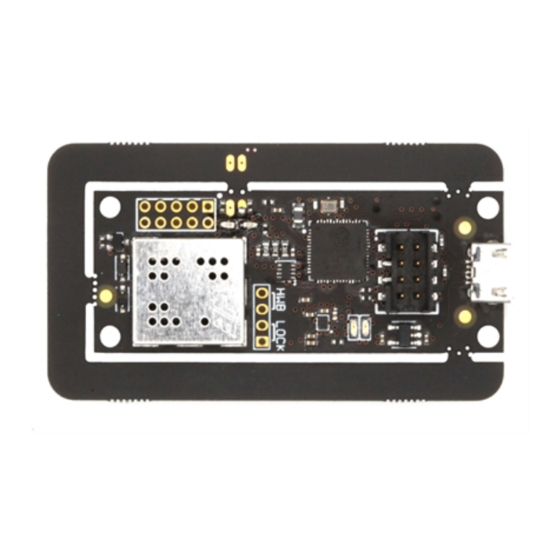
3 Mechanical installation The VTAP50 unit for OEM integration comprises a PCB with an integral antenna around the perimeter of the board. Figure 3-1 VTAP50 components - v1 Hardware WARNING: Observe all Safety instructions when installing the VTAP50 PCB. -
Page 10: Mounting Points
The PCB has 2.7mm diameter mounting holes for fixing the unit. Use 2-4 small nuts and bolts to mount the board securely. Figure 3-2 VTAP50 PCB mounting holes - v1 Hardware The user’s smartphone should be able to tap within 10mm of the antenna on the PCB. The antenna position should be clearly marked and easily accessed, so that users can position their smartphone appropriately. -
Page 11: Optional Captive Cable Connection - Rs232 And Usb
Figure 3-3 VTAP50 captive power cable or RS232 connection - VTAP50 v1 Rev 2 Hardware onwards CAUTION: There are a small number of VTAP50 v1 Rev 1 units in circulation. Please be aware that the pins on v1 Rev 1 hardware are pairwise switched. - Page 12 DCE and DTE devices, so that the transmit pin on one connects to the receive pin on the other. The VTAP50 requires a 5V power supply, but not all RS232 devices have 5V on pin 9. Either: Disconnect the USB cable before making the serial connection, if power will be provided by J1 (pins 1 and 3) and the serial cable/host.
-
Page 13: Module Integration Instructions
4 Module integration instructions The VTAP50 OEM module has been designed to comply with the limits for a Class B digital device, pursuant to Part 15 of the FCC Rules. Operation is subject to the following two conditions: (1) This device may not cause harmful interference. -
Page 14: Antennas
4.7 Additional testing requirements The VTAP50 OEM module will only be FCC authorised for use in compliance with the specific FCC transmitter rules listed on the grant. The integrator is responsible for compliance to any other FCC rules that apply to the host, which are not covered by the modular transmitter grant of certification. -
Page 15: Hardware Lock To Disable Usb Mass Storage Device
A software lock prevents changes but leaves some files visible. A hardware lock means that the VTAP50 will no longer be detected as a USB mass storage device. (It will still behave as an HID keyboard device and, if enabled, the virtual COM port will behave as a composite USB device consisting of HID keyboard and USB virtual COM port.) -
Page 16: Disposal
6 Disposal For safety and sustainability, it is the responsibility of the integrator to ensure that when equipment containing a VTAP50 reaches the end of its life, it is recycled in accordance with WEEE Regulations within the EU. VTAP50 (PCB and cables) should not be disposed of in general waste. If you wish to discard electrical and electronic equipment (EEE), please contact your supplier for further information.
Need help?
Do you have a question about the VTAP50 and is the answer not in the manual?
Questions and answers