Table of Contents
Advertisement
Available languages
Available languages
Quick Links
Bedienungsanleitung
DMM Leitungszuordnungsgerät LZG-1
Best.-Nr. 2527034
Operating Instructions
DMM Cable Allocator LZG-1
Item No. 2527034
Notice d'emploi
Identificateur de conduits avec DMM
LZG-1
N° de commande 2527034
Gebruiksaanwijzing
DMM Leidingidentificatie-Apparaat
LZG-1
Bestelnr. 2527034
Seite 2 - 21
Page 22 - 41
Page 42 - 61
Pagina 62 - 81
Advertisement
Chapters
Table of Contents

Related Manuals for VOLTCRAFT LZG-1


Summary of Contents for VOLTCRAFT LZG-1
- Page 1 Bedienungsanleitung DMM Leitungszuordnungsgerät LZG-1 Best.-Nr. 2527034 Seite 2 - 21 Operating Instructions DMM Cable Allocator LZG-1 Item No. 2527034 Page 22 - 41 Notice d’emploi Identificateur de conduits avec DMM LZG-1 N° de commande 2527034 Page 42 - 61 Gebruiksaanwijzing...
-
Page 2: Table Of Contents
Inhaltsverzeichnis Seite Einführung ................................3 Symbol-Erklärung ..............................4 Bestimmungsgemäße Verwendung ........................5 Lieferumfang ................................6 Sicherheitshinweise .............................6 Bedienelemente ..............................8 Produktbeschreibung ............................9 Display-Angaben und Symbole .........................10 Messbetrieb Multimeter (DMM) .........................10 a) Messgerät einschalten ..........................11 b) Spannungsmessung „V“ ..........................11 c) Widerstandsmessung „Ω” ..........................12 d) Diodentest ..............................12 e) Durchgangsprüfung .............................13 10. -
Page 3: Einführung
® Aufgaben gerecht. Voltcraft bietet Ihnen zuverlässige Technologie zu einem außergewöhnlich günstigen Preis-Leis- tungs-Verhältnis. Wir sind uns sicher: Ihr Start mit Voltcraft ist zugleich der Beginn einer langen und guten Zusammenarbeit. ® Viel Spaß mit Ihrem neuen Voltcraft -Produkt! Um diesen Zustand zu erhalten und einen gefahrlosen Betrieb sicherzustellen, müssen Sie als Anwender diese Bedienungsanleitung beachten! Diese Bedienungsanleitung gehört zu diesem Produkt. -
Page 4: Symbol-Erklärung
2. Symbol-Erklärung Das Symbol mit dem Blitz im Dreieck wird verwendet, wenn Gefahr für Ihre Gesundheit besteht, z.B. durch einen elektrischen Schlag. Das Symbol mit dem Ausrufezeichen im Dreieck weist auf wichtige Hinweise in dieser Bedienungsanlei- tung hin, die unbedingt zu beachten sind. Das Pfeil-Symbol ist zu finden, wenn Ihnen besondere Tipps und Hinweise zur Bedienung gegeben werden sollen. -
Page 5: Bestimmungsgemäße Verwendung
- Akustischer Durchgangsprüfer (< 100 Ohm, im Leitungszuordnungsmodus) Die Messfunktionen werden über den Drehschalter angewählt. In allen Messbereichen ist die automatische Mess- bereichswahl aktiv. Das Gehäuse des LZG-1 DMM enthält zwei unab- hängig arbeitende Funktionsteile. Das Lei-tungszu- ordnungsgerät (Empfänger) „A“ weist gegenüber dem Multimeterteil (DMM) „B“... -
Page 6: Lieferumfang
4. Lieferumfang • Digital-Multimeter mit Gummiholster (LZG-1 DMM) • Remote-Einheit (LZG-1 REMOTE UNIT) • 1 Blockbatterie 9V, 2 Micro-Batterien (AAA) • Sicherheitsmessleitungen rot und schwarz • Bedienungsanleitung Aktuelle Bedienungsanleitungen Laden Sie aktuelle Bedienungsanleitungen über den Link www.conrad.com/downloads herunter oder scannen Sie den abgebildeten QR-Code. Befolgen Sie die Anweisungen auf der Webseite. - Page 7 Vor jedem Wechsel des Messbereiches sind die Messspitzen vom Messobjekt zu entfernen. Seien Sie besonders Vorsichtig beim Umgang mit Spannungen >25 V Wechsel- (AC) bzw. >35 V Gleich- spannung (DC)! Bereits bei diesen Spannungen können Sie bei Berührung elektrischer Leiter einen le- bensgefährlichen elektrischen Schlag erhalten.
-
Page 8: Bedienelemente
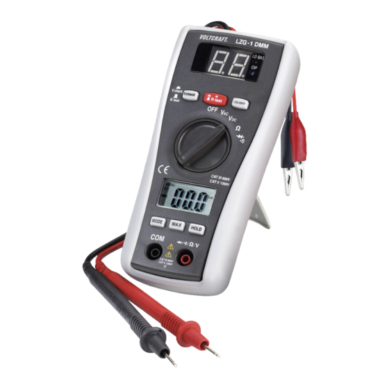
6. Bedienelemente 1 Display (LED) für Leitungszuordnung, Durchgangsprüfer und Polaritätstest 2 Umschalttaste Durchgangsprüfer und Leitungszuordnung (R = Receiver = Empfänger) 3 Umschalttaste Leitungszuordnung (R = Receiver = Empfänger) und Polaritätstest (V check) 4 Drehschalter 5 Display (LCD) für Multimeter 6 MODE-Taste zum Umschalten der Messfunktionen Diodentest und Durchgangsprüfer 7 COM-Messbuchse (Bezugsmasse, Minuspotenzial) 8 V-Messbuchse für alle Messfunktionen des Multimeters (Pluspotenzial) 9 HOLD-Taste zum „Einfrieren“... -
Page 9: Produktbeschreibung
11 Rückseitiges Batteriefach 12 Abnehmbarer Gummi-Schutzrahmen mit rückseitigem Aufstellbügel 13 ON/OFF-Taste zum Ein- und Ausschalten der Leitungszuordnungs-Anzeige 14 Messleitungen für Leitungszuordnung und Polarit tstest (rot = Pluspol, schwarz = Bezugspotenzial) 15 Rückseitiges Batteriefach 16 Betriebsschalter für Remote-Einheit (gedrückt = Ein) 17 Betriebsanzeige „OP“... -
Page 10: Display-Angaben Und Symbole
8. Display-Angaben und Symbole Dies ist eine Aufstellung aller möglichen Symbole und Angaben am DMM. AUTO Automatische Bereichswahl ist aktiv HOLD Data-Hold-Funktion ist aktiv Overload = Überlauf; der Messbereich wurde überschritten Aus-Position. Das DMM ist ausgeschaltet Symbol für Batteriewechsel Symbol für den Diodentest Symbol für den akustischen Durchgangsprüfer Symbol für „Taste nicht gedrückt“... -
Page 11: A) Messgerät Einschalten
a) Messgerät einschalten Das Messgerät wird über den Drehschalter (4) eingeschaltet. Drehen Sie den Drehschalter in die entsprechende Messfunktion. Zum Ausschalten bringen Sie den Drehschalter in Position „OFF“. Schalten Sie das Messgerät bei Nichtgebrauch immer aus (Position „OFF“). Bevor Sie mit dem Messgerät arbeiten können, müssen erst die beiliegenden Batterien eingesetzt werden. -
Page 12: C) Widerstandsmessung „Ω
c) Widerstandsmessung „Ω” Vergewissern Sie sich, dass alle zu messenden Schaltungsteile, Schaltungen und Bauelemente sowie andere Messobjekte unbedingt spannungslos und entladen sind. Zur Widerstandsmessung gehen Sie wie folgt vor: - Schalten Sie das DMM ein und wählen den Messbereich „Ω“. - Stecken Sie die rote Messleitung in die Ω -Messbuchse (8), die schwarze Messleitung in die COM-Messbuchse (7). - Überprüfen Sie die Messleitungen auf Durchgang, indem Sie die beiden Messspitzen verbinden. -
Page 13: E) Durchgangsprüfung
e) Durchgangsprüfung Vergewissern Sie sich, dass alle zu messenden Schaltungsteile, Schaltungen und Bauelemente sowie andere Messobjekte unbedingt spannungslos und entladen sind - Schalten Sie das DMM ein und wählen den Messbereich - Drücken Sie die Taste „MODE“ (6), um die Messfunktion umzuschalten. Im Dis- play erscheint das Symbol für Durchgangsprüfung. -
Page 14: Messbetrieb Leitungszuordnung
10. Messbetrieb Leitungszuordnung Überschreiten Sie auf keinen Fall die max. zulässige Eingangsgröße von 16 V/DC. Berühren Sie keine Schaltungen oder Schaltungsteile, wenn darin höhere Spannungen als 25 V ACrms oder 35 V DC anliegen können! Lebensgefahr! Kontrollieren Sie vor Messbeginn die fest angeschlossenen Messleitungen auf Beschädigungen wie z.B. -
Page 15: C) Dc-Polaritätstest
c) DC-Polaritätstest Die Empfängereinheit kann an Kleinspannungen von 5 bis 16 V/DC die Polarität ermitteln. Zur Durchgangsprüfung gehen Sie wie folgt vor: - Schalten Sie die Empfängereinheit durch Drücken des Schalters „ON/OFF“ (13) ein. Der Schalter rastet ein und die LED-Anzeige (1) zeigt „00“. Die Be- triebsanzeige „OP“... -
Page 16: Behebung Von Störungen
Zur Leitungszuordnung gehen Sie wie folgt vor: - Schalten Sie die Empfängereinheit durch Drücken des Schal- ters „ON/OFF“ (13) ein. Der Schalter rastet ein und die LED- Anzeige (1) zeigt „00“. Die Betriebsanzeige „OP“ leuchtet. - Drücken Sie an der „Remote-Einheit den Betriebsschalter (16). -
Page 17: Reinigung Und Wartung
12. Reinigung und Wartung a) Allgemein Um die Genauigkeit des Multimeters über einen längeren Zeitraum zu gewährleisten, sollte es jährlich einmal kalibriert werden. Das Messgerät ist bis auf eine gelegentliche Reinigung und den Batteriewechsel absolut wartungsfrei. Den Batterie- wechsel finden Sie im Anschluss. Überprüfen Sie regelmäßig die technische Sicherheit des Gerätes und der Messleitungen z.B. auf Beschädigung des Gehäuses oder Quetschung usw. - Page 18 Zum Einsetzen/Wechseln der Batterien im DMM gehen Sie wie folgt vor: - Trennen Sie Ihr Messgerät von allen Messkreisen und schalten es aus. - Entfernen Sie den Gummischutzrahmen (12) vom Gerät. - Lösen Sie die beiden Schrauben des Batteriefachdeckels (11) und ziehen diesen vom Gerät - Setzen Sie neue Batterien polungsrichtig in das Fach.
-
Page 19: Entsorgung
13. Entsorgung a) Produkt Alle Elektro- und Elektronikgeräte, die auf den europäischen Markt gebracht werden, müssen mit diesem Symbol gekennzeichnet werden. Dieses Symbol weist darauf hin, dass dieses Gerät am Ende seiner Lebensdauer getrennt von unsortiertem Siedlungsabfall zu entsorgen ist. Jeder Besitzer von Altgeräten ist verpflichtet, Altgeräte einer vom unsortierten Siedlungsabfall getrennten Erfassung zuzuführen. Die Endnutzer sind verpflichtet, Altbatterien und Altakkumulatoren, die nicht vom Altgerät umschlossen sind, sowie Lampen, die zerstörungsfrei aus dem Altgerät entnommen werden kön-... -
Page 20: Technische Daten
14. Technische Daten Anzeige .............LCD, 2000 Counts (Zeichen) Messleitungslänge ..........je ca. 80 cm Messimpedanz ..........>7,5 MΩ (V-Bereich) Automatische Abschaltung .......ca. 15 Minuten Betriebsspannung ..........DMM 2 x Micro-Batterie (AAA) ................Empfänger 9V Blockbatterie ................Sender 9V Blockbatterie Arbeitsbedingungen ..........0 bis 40°C (<75%rF) Betriebshöhe ............max. 2000 m Lagertemperatur ..........-10°C bis +50°C (<80%rF) Gewicht .............DMM ca. - Page 21 Überlastschutz: 600 V; Impedanz >7,5 MΩ Wechselspannung V/AC Auflösung Bereich Genauigkeit 0,001 V ±(1,3% + 6) 20 V 0,01 V 200 V 0,1 V ±(1,8% + 10) 600 V Frequenzbereich 50 – 60 Hz; Mittelwert bei Sinus-Spannung; Überlastschutz 600 V; Impedanz >7,5 MΩ Widerstand Ω Auflösung Bereich Genauigkeit 200 Ω 0,1 Ω ±(1,0% + 6) 2 kΩ 0,001 kΩ 20 kΩ 0,01 kΩ ±(1,5% + 4) 200 kΩ...
- Page 22 Table of Contents Page Introduction ................................23 Description of symbols ............................24 Intended use ..............................25 Delivery content ..............................26 Safety instructions .............................26 Operating Elements ............................28 Product Description ............................29 Display Indications and Symbols ........................30 Measuring with the Multimeter (DMM) .......................30 a) Turning the measuring device on ........................31 b) Voltage measuring “V”...
-
Page 23: Introduction
Voltcraft offers you reliable technology at an extraordinarily favourable cost-performance ratio. Therefore, we are absolutely sure: starting to use Voltcraft will also be the beginning of a long, successful relationship. ® We hope you will enjoy using your new Voltcraft... -
Page 24: Description Of Symbols
2. Description of symbols The triangle containing a lightning symbol warns of danger of an electric shock or of the impairment of the electrical safety of the device. An exclamation mark in a triangle indicates important notices in these operating instructions which have to be observed under all circumstances!d. -
Page 25: Intended Use
- Acoustic continuity tester (< 100 Ohm, in cable allocation mode) The measuring functions are selected via a rotary switch. Automatic measuring range selection is active in all measu- ring ranges. The housing of the LZG-1 DMM contains two func- tion components that work independently of each other. The cable allocator (receiver) “A” has a fuse disconnector for shielding from the multimeter com- ponent (DMM) “B”. Both components work indepen-... -
Page 26: Delivery Content
4. Delivery content • Digital multimeter with rubber holster (LZG-1 DMM) • Remote unit (LZG-1 REMOTE UNIT) • 1 compound batterie (9V), 2 micro batteries (AAA) • Safety measuring cables red and black • Operating instructions Up-to-date operating instructions Download the latest operating instructions at www.conrad.com/downloads or scan the QR code shown. - Page 27 Be especially careful when dealing with voltages higher than 25V AC or 35 V DC. Even at such voltages you can receive a life-threatening electric shock when you come into contact with electric wires. Check the measuring device and its measuring lines for damage before each measurement. Never carry out any measurements if the protecting insulation is defective (torn, ripped off etc.).
-
Page 28: Operating Elements
6. Operating Elements 1 Display (LED) for cable allocation, continuity tester and polarity test 2 Toggle key continuity tester and cable allocation (R = receiver) 3 Toggle key cable allocation (R = receiver) and polarity test (V check) 4 Rotary switch 5 Display (LCD) for multimeter 6 MODE button for switching the measuring functions diode test and continuity tester 7 COM measuring socket (reference mass, minus potential) -
Page 29: Product Description
11 Battery compartment on the rear 12 Removable protective rubber frame with setup brackets on the rear 13 ON/OFF button for activating/deactivating the cable allocation display 14 Measuring leads for cable allocation and polarity test (red = positive pole, black = reference potential) 15 Battery compartment at rear 16 Duty switch for remote unit (depressed = on) 17 Operating indicator “OP”... -
Page 30: Display Indications And Symbols
8. Display Indications and Symbols This is a list of all possible symbols and statements on the DMM. AUTO Automatic range selection is active HOLD Data hold function is activated Overload, the measuring range was exceeded Off position. The DMM is switched off. Symbol for battery change Symbol for the diode test Symbol for the acoustic continuity tester... -
Page 31: A) Turning The Measuring Device On
a) Turning the measuring device on The measuring instrument is turned on again via the rotary switch (4). Turn the rotary switch to the desired measuring function. Turn the rotary switch to “OFF” to turn the device off. Always turn the measuring device off when it is not in use (position “OFF”). Prior to working with the measuring device, you first have to insert the enclosed batteries. Inserting and changing the battery is described in the chapter “Maintenance and cleaning”. -
Page 32: C) Resistance Measurement "Ω
c) Resistance measurement “Ω” Make sure that all the circuit parts, switches and components and other objects of measurement are disconnected from the voltage and discharged. Proceed as follows to measure the resistance: - Turn the DMM on and select measuring range “Ω”. - Plug the red measuring lead into the Ω measuring socket (8) and the black measuring lead into the COM measuring socket (7). - Check the measuring leads for continuity by connecting both measuring prods with one another. -
Page 33: E) Continuity Check
e) Continuity check Make sure that all the circuit parts, switches and components and other objects of measurement are disconnected from the voltage and discharged. - Turn the DMM on and select measuring range - Press the button “MODE” (6) to switch the measuring function. The symbol for continuity check now appears in the display. Pressing this button again takes you to the first measuring function etc. -
Page 34: Measuring Mode Line Allocation
10. Measuring mode line allocation In no event exceed the max. permitted input value of 16 V/DC. Do not contact circuits or parts of circuits if there could be voltages higher than 25 V ACrms or 35 V DC present within them. Mortal danger! Before measuring, check the permanently connected measuring lines for damage such as, for ex- ample, cuts, cracks or squeezing. -
Page 35: C) Dc Polarity Test
c) DC polarity test The receiver unit can determine the polarity of low voltages of 5 to 16 V/DC. Proceed as follows to perform the continuity test: - Switch the receiver unit on by pressing the switch “ON/OFF” (13). The switch snaps into place and the LED display (1) shows “00”. The operating indicator “OP” will light up. If “OP” is not lit, please press the button “R test” (2) to release it. -
Page 36: Troubleshooting
Proceed as follows for the line allocation: - Switch the receiver unit on by pressing the switch “ON/OFF” (13). The switch snaps into place and the LED display (1) shows “00”. The operating indicator “OP” will light up. - On the remote unit, press the duty switch (16). The operating indicator “OP” blinks. - Contact the black banana clips (reference lines) with each other via a know line. -
Page 37: Cleaning And Maintenance
12. Cleaning and maintenance a) General To ensure the accuracy of the multimeter over an extended period of time, it should be calibrated once a year. Apart from occasional cleaning and battery replacements, the multimeter requires no servicing. The battery change is described below. Regularly check the technical safety of the instrument and measuring lines, e.g. - Page 38 To insert/replace the batteries in the DMM, proceed as follows: - Disconnect the measuring device from all measuring cir- cuits and turn it off. - Remove the protective rubber frame (12) from the device. - Undo the screws on the battery compartment cover (11) and remove the cover.
-
Page 39: Disposal
13. Disposal a) Product All electrical and electronic equipment placed on the European market must be labelled with this symbol. This symbol indicates that this device should be disposed of separately from unsorted municipal waste at the end of its service life. All owners of waste equipment are obliged to dispose of waste equipment separately from unsorted mu- nicipal waste. -
Page 40: Technical Data
14. Technical data Display ..............LCD; 2000 counts Measuring cable length ........about 80 cm each Measuring impedance ........>7.5 MΩ (V range) Automatic switch-off .........approx. 15 minutes Operating voltage ..........DMM 2 x micro batteries (AAA) ................Receiver 9V block battery ................Transmitter 9V block battery Working conditions ...........0 to 40°C (<75%rh) Operating altitude ..........max. - Page 41 Alternating voltage V/AC Range Resolution Accuracy 0.001 V ±(1.3% + 6) 20 V 0.01 V 200 V 0.1 V ±(1.8% + 10) 600 V Frequency range 50 – 60 Hz; average value with sinus voltage; overload protection 600 V; impedance >7.5 MΩ Resistance Ω Range Resolution Accuracy 200 Ω 0.1 Ω ±(1.0% + 6) 2 kΩ 0.001 kΩ 20 kΩ 0.01 kΩ ±(1.5% + 4) 200 kΩ...
- Page 42 Table des matières Page Introduction ................................43 Explication des symboles ..........................44 Utilisation conforme ............................45 Contenu de l’emballage .............................46 Consignes de sécurité ............................46 Eléments de commande ............................48 Description du produit ............................49 Indications apparaissant à l´écran et symboles ....................50 Mode de mesure multimètre (DMM) ........................50 a) Mise en marche de l´instrument de mesure ....................51 b) Mesure de tension «...
-
Page 43: Introduction
® ® Voltcraft permet de répondre aux tâches exigeantes du bricoleur ambitieux ou de l’utilisateur professionnel. Voltcraft vous offre une technologie fiable à un rapport qualité-prix particulièrement avantageux. Nous en sommes convaincus : votre premier contact avec Voltcraft marque le début d’une coopération efficace de longue durée. Nous vous souhaitons beaucoup de plaisir avec votre nouveau produit Voltcraft ®... -
Page 44: Explication Des Symboles
2. Explication des symboles Le symbole de l’éclair dans un triangle met en garde contre tout risque de décharge électrique ou toute compromission de la sécurité électrique de l’appareil. Dans ce mode d’emploi, un point d’exclamation placé dans un triangle signale des informations importan- tes à... -
Page 45: Utilisation Conforme
- Contrôleur de continuité acoustique (<100 ohms, en mode identification de conduits) Les fonctions de mesure peuvent être sélectionnées via le commutateur rotatif. La sélection automatique est activée dans toutes les plages de mesuure. Le boîtier du DMM LZG-1 comprend deux parties qui fonctionnent de façon autonome. L’identificateur de conduits (récepteur) “A” dispose d’une séparati- on de protection par rapport au multimètre (DMM) “B”. Les deux parties de l´appareil fonctionnent in-... -
Page 46: Contenu De L'emballage
4. Contenu de l’emballage • Multimètre numérique avec gaine caoutchouc (LZG-1 DMM) • Unité Remote (REMOTE UNIT LZG-1) • 1 piles blocs 9V, 2 piles Micro (type AAA) • Ligne de mesure de sûreté rouge et noire • Notice d’utilisation Mode d’emploi actualisé... - Page 47 Ne pas appliquer de tensions supérieures à 16 V/DC aux pinces crocodile de la partie identificateur de conduits (14 et 19). Ces pinces sont prévues uniquement pour les tensions de signal et de commande et pour les câbles hors tension. Eloignez les pointes de mesure de l’objet à mesurer avant de changer de plage de mesure. Une prudence particulière est conseillée en présence de tensions alternatives (AC) supérieures à...
-
Page 48: Eléments De Commande
6. Eléments de commande 1 Indicateur (LED) pour idenfication de conduits, contrôleur de continuité et test de polarité 2 Touche de commutation pour contrôleur de continuité et identificateur de conduits (R = receiver = récepteur) 3 Touche de commutation pour identificateur de conduits (R = receiver = récepteur) et test de polarité (check V) 4 Bouton rotatif 5 Ecran (LCD) du multimètre 6 Touche MODE pour commuter les fonctions de mesure du test de diodes et du contrôleur de continuité 7 Douille de mesure COM (masse de référence, potentiel négatif) 8 Douille de mesure V pour toutes les fonctions de mesure du multimètre (potentiel positif) 9 Touche HOLD pour “geler” la valeur affichée à l´écran 10 Touche MAX;... -
Page 49: Description Du Produit
11 Compartiment pour piles sur la face arrière 12 Cadre de protection en caoutchouc amovible et pied au dos 13 Touche ON/OFF pour allumer et éteindre l´affichage de l´identificateur de conduits 14 Câbles de mesure pour l´identification de conduits et le test de polarité (rouge = pôle positif, noir = potentiel de référence) 15 Logement des piles au dos 16 Interrupteur de service de l´unité Remote (enfoncé = en marche) 17 Indicateur de fonctionnement “OP”... -
Page 50: Indications Apparaissant À L´écran Et Symboles
8. Indications apparaissant à l´écran et symboles Liste de tous les symboles et indications possibles du DMM. AUTO La sélection automatique de la plage de mesure est activée HOLD Fonction Data Hold activée Overload = Dépassement; la plage de mesure a été dépassée Position éteinte. -
Page 51: A) Mise En Marche De L´instrument De Mesure
a) Mise en marche de l´instrument de mesure L’appareil de mesure se met en marche via le sélecteur rotatif (4). Tournez le bouton rotatif pour l´amener dans la position de mesure correspondante. Pour l´éteindre, mettez le bouton rotatif en position « OFF ». Eteignez toujours l´appareil de mesure en cas d´inutilisation (position “OFF“). -
Page 52: C) Mesure De Résistance "Ω
c) Mesure de résistance “Ω” Assurez-vous que tous les éléments du circuit, tous les circuits, composants à mesurer et autres objets de mesure sont impérativement hors tension et déchargés.. Pour la mesure de la résistance, procédez comme suit : - Allumez le DMM et choisissez la plage de mesure “Ω”. - Enfichez le câble de mesure rouge dans la douille de mesure Ω (8) et le câble noir dans la douille COM (7). -
Page 53: E) Contrôle De Continuité
e) Contrôle de continuité Assurez-vous que tous les éléments du circuit, tous les circuits, composants à mesurer et autres objets de mesure sont impérativement hors tension et déchargés. - Allumez le DMM et choisissez la plage de mesure - Pour commuter dans la fonction de mesure, appuyez sur la touche “MODE” (6). Le symbole du contrôle de continuité s’affiche sur l’écran ! Une nouvelle pression sur la touche vous fait accéder à... -
Page 54: Mode De Mesure Identificateur De Conduits
10. Mode de mesure identificateur de conduits Ne dépassez en aucun cas les grandeurs d’entrée maximales autorisées de 16V/DC. Ne touchez aucun circuit ou aucune partie des circuits en présence de tensions supérieures à 25 V ACrms ou à 35 V DC. Danger de mort ! Avant le début de la mesure, assurez-vous de l’absence d’endommagements tels que des cou- pures, fissures ou pincements au niveau des câbles de mesure raccordés. -
Page 55: C) Test De Polarité Dc
c) Test de polarité DC Le récepteur peut déterminer la polarité des très basses tensions comprises entre 5 et 16 V/DC. Pour le test de polarité, procédez comme suit : - Mettez le récepteur alarme en marche en appuyant sur l’interrupteur “ON/ OFF (13). L’interrupteur s´enclenche et l’indicateur DEL (1) affiche “00”. -
Page 56: Dépannage
Procédez comme suit pour identifier les conduits : - Mettez le récepteur alarme en marche en appuyant sur l’interrupteur “ON/OFF (13). L’interrupteur s´enclenche et l’indicateur DEL (1) affiche “00”. L´indicateur de fonctionne- ment “OP” s´allume. - Appuyez sur l’interrupteur de service de l´unité Remote (16). L´indicateur de fonctionnement “OP” clignote. - Connectez les pinces croco noires (conduits de ré féren - ces) ensemble via un conduit connu. -
Page 57: Nettoyage Et Maintenance
12. Nettoyage et maintenance a) Généralités Afin de garantir la précision du multimètre pendant une période prolongée, il doit être calibré une fois par an. Hormis le nettoyage occasionnel et le remplacement des piles, l´instrument de mesure ne nécessite pas d’entretien. Vous trouverez le chapitre concernant le remplacement des piles ci-après. Contrôlez régulièrement la sécurité technique de l’appareil et des câbles de mesure en vous assu- rant de l’absence d’endommagements au niveau du boîtier ou d’écrasement, etc. - Page 58 Pour remplacer les piles du DMM, procédez comme suit : - Coupez votre appareil de mesure de tous les circuits de mesure et éteignez-le. - Retirez le cadre de protection en caoutchouc (12) de l’appareil. - Desserrez les deux vis du couvercle du logement des piles (11) et retirez-le de l’appareil.
-
Page 59: Élimination
13. Élimination a) Produit Tous les équipements électriques et électroniques mis sur le marché européen doivent être marqués de ce symbole. Ce symbole indique que cet appareil doit être éliminé séparément des déchets municipaux non triés à la fin de son cycle de vie. Tout détenteur d'appareils usagés est tenu de les remettre à un service de collecte séparé des déchets municipaux non triés. Les utilisateurs finaux sont tenus de séparer, sans toutefois les détruire, les piles et accumulateurs usagés qui ne sont pas intégrés dans l'appareil usagé, ainsi que les lampes qui peuvent être enlevées de l'appareil usagé... -
Page 60: Caractéristiques Techniques
14. Caractéristiques techniques Affichage ............LCD, 2000 Counts (signes) Longueur des câbles de mesure ......env. 80 cm chacun Impédance de mesure ........>7,5 MΩ (plage V) Désactivation automatique .......env. 15 minutes Tension de service ..........DMM 2 x piles micro (AAA) ................Récepteur Pile bloc de 9V ................Emetteur Pile bloc de 9V Conditions de travail .........0 à... - Page 61 Tension alternative V/AC Résolution Plage Précision 0,001 V ±(1,3% + 6) 20 V 0,01 V 200 V 0,1 V ±(1,8% + 10) 600 V Gamme de fréquence 50 – 60 Hz; moyenne pour tension sinusoïdale; protection contre les surcharges 600 V; impédance >7,5 MΩ...
- Page 62 Inhoudsopgave Pagina Inleiding ................................63 Verklaring van de symbolen ..........................64 Conform gebruik ..............................65 Leveringsomvang ..............................66 Veiligheidsinstructies ............................66 Bedieningselementen ............................68 Productbeschrijving ............................69 Displaygevens en symbole ..........................70 Meten met de multimeter (DMM) ........................70 a) Meetapparaat inschakelen ..........................71 b) Spanningsmeting „V“ ...........................71 c) Weerstandsmeting „Ω”..........................72 d) Diodentest ..............................72 e) Doorgangstest .............................73 10. Meetbedrijf leidingidentificatie ..........................74...
-
Page 63: Inleiding
Voltcraft biedt u betrouwbare technologie met een buitengewoon gunstige verhouding van prijs en prestaties. Wij zijn zeker dat uw start met Voltcraft is tegelijkertijd het begin van een lange en goede samenwerking. ® Veel plezier met uw nieuwe Voltcraft... -
Page 64: Verklaring Van De Symbolen
2. Verklaring van de symbolen Een bliksemschicht in een driehoek waarschuwt voor een elektrische schok of een negatieve beïnvloeding van de elektrische veiligheid van het apparaat.g. Een uitroepteken in een driehoek wijst op belangrijke instructies in deze gebruiksaanwijzing die absoluut opgevolgd dienen te worden. -
Page 65: Conform Gebruik
- Akoestische doorgangstest (< 100 Ohm, in leidingidentificatiemodus) De afzonderlijke meetbereiken worden gekozen via de draaischakelaar. Op alle meetbereiken is die automatische meetbereikkeuze actief. De behuizing van de LZG-1 DMM bevat twee onaf- hankelijk werkende delen. Het leidingidentificatie- apparaat (ontvanger) „A“ is geïsoleerd van het mul- timeterdeel (DMM) „B“. -
Page 66: Leveringsomvang
4. Leveringsomvang • Digitale multimeter met rubberholster (LZG-1 DMM) • Remote eenheid (LZG-1 REMOTE UNIT) • 1 blokbatterij 9V, 2 microbatterijen (type AAA) • Veiligheidsmeetsnoeren rood en zwart • Gebruiksaanwijzing Actuele gebruiksaanwijzingen Download de meest recente gebruiksaanwijzing via de onderstaande link www.conrad.com/down- loads of scan de afgebeelde QR-code. - Page 67 Vóór elke wisseling van het meetbereik moeten de meetstiften van het meetobject worden verwijderd. Wees vooral voorzichtig bij de omgang met spanningen >25 V wissel- (AC) resp. >35 V gelijkspanning (DC)! Reeds bij deze spanningen kunt u door het aanraken van elektrische geleiders een levensgevaarlijke elektrische schok krijgen.
-
Page 68: Bedieningselementen
6. Bedieningselementen 1 Display (LED) voor leidingidentificatie, doorgangstest en polariteitstest 2 Omschakeltoets doorgangstest en leidingidentificatie (R = receiver = ontvanger) 3 Omschakeltoets leidingsidentificatie (R = receiver = ontvanger) en polariteitstest (V check) 4 Draaischakelaar 5 Display (LCD) voor multimeter 6 MODE-toets voor het omschakelen van de meetfuncties ‘diodetest’ en ‘doorgangstest’ 7 COM-meetbus (referentiemassa, minpotentiaal) 8 V-meetbus voor alle meetfuncties van de multimeter (plus-potentiaal) 9 HOLD-toets voor het „bevriezen“ van de weergegeven displaywaarde 10 MAX-toets;... -
Page 69: Productbeschrijving
11 Batterijvak aan achterzijde 12 Afneembare rubber-bescherming met beugel op de achterzijde 13 ON/OFF-toets voor het in- en uitschakelen van de leidingidentificatie-weergave 14 Meetsnoeren voor leidingidentificatie en polariteitstest (rood = pluspool, zwart = referentiepotentiaal) 15 Batterijvak aan de achterzijde 16 Functieschakelaar voor de remote-eenheid (ingedrukt = aan) 17 Bedrijfsindicatie „OP“ 18 Indicatie vervangen batterijen „LO BAT“ 19 Identificatieleidingen (zwart = G (referentieleiding), rood = code 1 – 16) 7. -
Page 70: Displaygevens En Symbole
8. Displaygevens en symbole Dit is een overzicht van alle mogelijke symbolen en indicaties op de DMM. AUTO Automatische instelling van het meetbereik actief HOLD De data hold-functie is actief. Overflow; het meetbereik werd overschreden Uit-positie. De DMM is uitgeschakeld. Batterij vervangen-symbool Symbool voor de diodetest Symbool voor de akoestische continuïteitsmeting Symbool voor „Toets niet ingedrukt”... -
Page 71: A) Meetapparaat Inschakelen
a) Meetapparaat inschakelen Het meetapparaat wordt via de draaischakelaar (4) opnieuw ingeschakeld. Plaats de draaischakelaar op de betrokken meetfunctie. Draai voor het uitschakelen de draaischakelaar in de stand „OFF“. Schakel het meetapparaat altijd uit wanneer u het niet gebruikt (stand „OFF“). Voordat u het meetapparaat kunt gebruiken, moet eerst de meegeleverde batterijen worden ge- plaatst. -
Page 72: C) Weerstandsmeting „Ω
c) Weerstandsmeting „Ω” Controleer of alle te meten schakeldelen, schakelingen en componenten evenals andere meetob- jecten absoluut spanningsloos en ontladen zijn. Voor de weerstandsmeting gaat u als volgt te werk: - Schakel de DMM in en kies het meetbereik “Ω”. - Steek het rode meetsnoer in de Ω-meetbus (8), het zwarte in de COM-aans- luiting (7). - Controleer de meetsnoeren op doorgang door beide meetpunten met elkaar te verbinden. -
Page 73: E) Doorgangstest
e) Doorgangstest Controleer of alle te meten schakeldelen, schakelingen en componenten evenals andere meetob- jecten absoluut spanningsloos en ontladen zijn. - Schakel de DMM in en kies het meetbereik - Druk op de toets „MODE“ (6) om de meetfunctie om te schakelen. Op het dis- play verschijnt het symbool door de doorgangsmeting. -
Page 74: Meetbedrijf Leidingidentificatie
10. Meetbedrijf leidingidentificatie Zorg dat de max. toelaatbare ingangsspanning van 16V/DC in geen geval wordt overschreden. Raak schakelingen en schakeldelen niet aan als daarop een hogere spanning dan 25 V ACrms of 35 V DC kan staan! Levensgevaarlijk! Controleer voor aanvang van de meting de aangesloten meetdraden op beschadigingen, zoals sneden, scheuren of afknellingen. -
Page 75: C) Dc-Polariteitstest
c) DC-polariteitstest De ontvangereenheid kan bij kleine spanningen van 5 tot 16 V/DC de polariteit bepalen. Voor een doorgangstest gaat u als volgt te werk: - Schakel de ontvangereenheid in door indrukken van de schakelaar „ON/ OFF“ (13). De schakelaar klikt in, en op het LED-display (1) wordt „00“ zicht- baar. -
Page 76: Verhelpen Van Storingen
Voor het identificeren van de leidingen gaat u te werk als volgt: - Schakel de ontvangereenheid in door indrukken van de scha- kelaar „ON/OFF“ (13). De schakelaar klikt in, en op het LED- display (1) wordt „00“ zichtbaar. De bedrijfsindicatie „OP“ wordt zichtbaar. -
Page 77: Reiniging En Onderhoud
12. Reiniging en onderhoud a) Algemeen Om de nauwkeurigheid van de multimeter over een langere periode te kunnen garanderen, moet het apparaat jaarlijks worden geijkt. Afgezien van een incidentele reinigingsbeurt en het vervangen van de batterij is het apparaat onderhoudsvrij. Het vervangen van de batterijen wordt hierna beschreven. - Page 78 Ga voor het plaatsen/vervangen van de batterijen in de DMM te werk als volgt: - Neem het meetapparaat los van alle meetkringen, en scha- kel het uit. - Verwijder de rubber houder (12) van het apparaat. - Draai de beide schroeven van het deksel van het batterij- vak (11) los en haal dit van het apparaat - Plaats nieuwe batterijen volgens de juiste poolrichting in het vak...
-
Page 79: Verhelpen Van Storingen
13. Verwijdering a) Product Alle elektrische en elektronische apparatuur die op de Europese markt wordt gebracht, moet met dit sym- bool zijn gemarkeerd. Dit symbool geeft aan dat dit apparaat aan het einde van zijn levensduur gescheiden van het ongesorteerd gemeentelijk afval moet worden weggegooid. Iedere bezitter van oude apparaten is verplicht om oude apparaten gescheiden van het ongesorteerd gemeentelijk afval af te voeren. -
Page 80: Technische Gegevens
14. Technische gegevens Indicatie ............LCD, 2000 counts (tekens) Lengte meetdraden ..........elk ca. 80 cm Meetimpedantie ..........>7,5 MΩ (V-bereik) Automatische uitschakeling ......ca. 15 Minuten Voedingsspanning ..........DMM 2 x micro-batterijen (AAA) ................Ontvanger 9V-blokbatterij ................Zender 9V-blokbatterij Bedrijfsvoorwaarden .........0 tot 40°C (<75% rv) Gebruikshoogte ..........max. 2.000 m Opslagtemperatuur ...........-10°C tot +50°C (<80% rv) Gewicht .............DMM ca. - Page 81 Wisselspanning V/AC Definitie Bereik Nauwkeurigheid 0,001 V ±(1,3% + 6) 20 V 0,01 V 200 V 0,1 V ±(1,8% + 10) 600 V Frequentiegebied 50 – 60 Hz; gemiddelde waarde bij een sinusvormige spanning; overbelastingsbescherming 600 V; Impedantie 7,5 MΩ Weerstand Ω Definitie Bereik Nauwkeurigheid 200 Ω...
- Page 84 Dies ist eine Publikation der Conrad Electronic SE, Klaus-Conrad-Str. 1, D-92240 Hirschau (www.conrad.com). Alle Rechte einschließlich Übersetzung vorbehalten. Reproduktionen jeder Art, z. B. Fotokopie, Mikroverfilmung, oder die Erfassung in elektronischen Datenverarbeitungsanlagen, bedürfen der schriftlichen Genehmigung des Herausgebers. Nachdruck, auch auszugsweise, verboten. Die Publikation entspricht dem technischen Stand bei Drucklegung. Copyright 2022 by Conrad Electronic SE.
Need help?
Do you have a question about the LZG-1 and is the answer not in the manual?
Questions and answers