Table of Contents
Advertisement
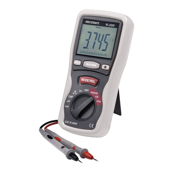
Milliohmmeter R-200
B E DI EN UNG SANLEI TUNG
R-200 Milliohm Meter
OPERATING INSTRUCTIONS
Milliohmmètre R-200
NOTICE D'EMPLOI
Milliohmmeter R-200
GEBRUIKSAANWIJ ZI NG
Best.-Nr. / Item-No. /
N° de commande / Bestnr.:
10 13 93
VOLTCRAFT
®
Seite 4 - 23
Page 24 - 43
Page 44 - 63
Pagina 64 - 83
°
Version 02/09
Advertisement
Table of Contents

Related Manuals for VOLTCRAFT R-200


Summary of Contents for VOLTCRAFT R-200
- Page 1 VOLTCRAFT ® Milliohmmeter R-200 B E DI EN UNG SANLEI TUNG Seite 4 - 23 R-200 Milliohm Meter OPERATING INSTRUCTIONS Page 24 - 43 Milliohmmètre R-200 NOTICE D’EMPLOI Page 44 - 63 Milliohmmeter R-200 GEBRUIKSAANWIJ ZI NG Pagina 64 - 83 Best.-Nr.
- Page 2 These operating instructions represent the technical status at the time of printing. Changes in technology and equipment reserved. © Copyright 2009 by Voltcraft ® Informations /légales dans nos modes d'emploi Ce mode d'emploi est une publication de la société Voltcraft ® , Lindenweg 15, D-92242 Hirschau/Allemagne, Tél. +49 180/586 582 7 (www.voltcraft.de).
- Page 3 Diese Bedienungsanleitung gehört zu diesem Produkt. Sie enthält wichtige Hinweise zur Inbetriebnahme und Handhabung. Achten Sie hierauf, auch wenn Sie dieses Produkt an Dritte weitergeben. Heben Sie deshalb diese Bedienungsanleitung zum Nachlesen auf! Eine Auflistung der Inhalte finden Sie in dem Inhaltsverzeichnis mit Angabe der entsprechenden Seitenzahlen auf Seite 4.
-
Page 5: Table Of Contents
With Voltcraft®, you will be able to cope even with difficult tasks as either an ambitious hobbyist or as a professional user. Voltcraft® offers you reliable technology and extremely good value for money. -
Page 6: Delivery Contents
Delivery Content Multimeter 2 safety measuring leads (red and black) 2 Kelvin measuring leads (red and black) 6 mignon batteries Plastic case Operating instructions Intended Use - Measuring and displaying electric parameters in the range of excess voltage category CAT III (up to max. -
Page 7: Controls
Controls (see fold-out page) 1 LCD display 2 MAX/MIN button for max/min value display 3 HOLD button to “freeze” the displayed values 4 MODE/REL button to switch to double-allocated measuring functions (AC/DC, continuity test and diode test) and relative measurement in low Ohm range 5 Dial switch 6 Light button to switch the display illumination on 7 Attachment fitting (for holding strap etc.) -
Page 8: Safety Instructions
Safety Instructions Please read all of the operating instructions before using the product for the first time; they contain important information about the correct operation. The warranty/guarantee is rendered void in cases of damage resulting from failure to comply with these operating instructions! We do not accept any liability for conse- quential damages! Nor do we assume liability for damage to property or personal injury caused by improper use or the failure to observe the safety instructions! In such cases the war-... - Page 9 Consult an expert when in doubt about the operation, the safety or the connection of the device. Measuring instruments and accessories are not toys and have no place in the hands of children! On industrial sites the accident prevention regulations of the association of the industrial workers’ soci- ety for electrical equipment and utilities must be followed.
-
Page 10: Product Description
Product Description The multimeter (referred to as DMM in the following) indicates measured values along with units and symbols on the digital display. The measuring value display of the DMM comprises 4000 counts (count = smallest display value). A bargraph shows rapid changes in values. If the DMM is not operated for approx. -
Page 11: Display Information And Symbols
Display Information and Symbols This is a summary of all possible symbols and information on the DMM AUTO Automatic range setting is active MANU Symbol for manual range setting HOLD Data-Hold function is active Overload = the measuring range was exceeded Off The DMM is switched off Symbol for battery change required Symbol for the diode test... -
Page 12: Measuring Mode
Measuring Mode Do not exceed the maximum permitted input values. Do not touch circuits or parts of circuits if there could be voltages higher than 25 V ACrms or 35 V DC present within them! Risk of fatal injury! Before measuring, check the connected measuring leads for damage such as, for example, cuts, cracks or squeezing. -
Page 13: C) Measuring Current "Μa/Ma
Proceed as follows to measure AC voltages “V/AC”: - Turn the DMM on and select measuring range “V”. - Press “MODE” (4) to switch to the AC measuring range. “AC” appears in the display. - Plug the red single measuring lead into the V measuring socket “E2” (10) and the black measuring lead into the COM measuring socket “E1”... -
Page 14: D) Measuring Capacity "Cap
Proceed as follows to measure AC currents (A/AC): - Turn the DMM on and select measuring range “µA” or “mA”. For currents >4 mA select the range “mA”, for currents <4 mA choose “µA”. - Press “MODE” (4) to switch to the AC measuring range. “AC” appears in the display. - Plug the red single measuring lead into the mA measuring socket “E2”... -
Page 15: E) Continuity Check
e) Continuity Check Make sure that all the circuit parts, switches and components and other objects of measurement are disconnected from the voltage and discharged. - Turn the DMM on and select measuring range - Press “MODE” (4) to switch measurement functions. The symbol for con- tinuity check now appears in the display. -
Page 16: G) Measuring Resistance "Ω
g) Resistance measurement “Ω Ω ” Make sure that all the circuit parts, switches and components and other objects of measurement are disconnected from the voltage and discharged. The Milliohm meter allows you to measure resistances in normal measurement ranges from 0.1 Ω to 40 MΩ... -
Page 17: Hold Function
Proceed as follows to measure the resistance using the 4-lead procedure: - Turn the DMM on and select measuring range “400 mΩ, 4Ωor 40Ω” depending on the measurement you are going to make. - Plug the red double-measuring lead (Kelvin measuring lead) into the Ω measuring socket “E2”... -
Page 18: Rel Function
REL Function The REL function is only active in the 4-lead resistance measurement ranges (400 mΩ Ω , 4Ω Ω or 40Ω Ω ). The REL function allows a fast relative measurement, e.g. to display component tolerances. The refer- ence component is measured and saved in the internal memory and then automatically deducted from subsequent measurements. -
Page 19: Switching On Display Illumination
Switching on Display Illumination The display can be illuminated in operating mode when the light conditions are bad. Press the light but- ton (6) to switch on the illumination. The lighting stays on for approx. 5s and then switches off automati- cally in order to protect the batteries. -
Page 20: Changing The Fuse
Proceed as follows to insert or change the batteries: - Disconnect all measuring leads from the meter and switch it off. - Fold out the mounting bracket (8) and unscrew the four screws securing the battery compartment (9). - Remove the cover of the battery compartment from the meter. -
Page 21: Disposal
Proceed as follows for fuse replacement: - Disconnect all measuring leads from the meter and switch it off. - Open the battery compartment as described in the chapter “Inserting and Changing the Batteries”. - The fuses can be accessed now. - Replace the defective fuse(s) with a new fuse of the same type and nominal voltage. -
Page 22: Troubleshooting
Repairs other than those described should only be carried out by an authorised spe- cialist. If you have queries about handling the measuring device, our technical sup- port is available under the following telephone number: Voltcraft®, 92242 Hirschau, Lindenweg 15, Tel.-No. 0180 / 586 582 7. Technical Data Display... - Page 23 Measurement tolerances Statement of accuracy in ± (% of reading + display error in counts (= number of smallest points)). The accuracy is valid for one year at a temperature of +23°C ± 5°C, and at a relative humidity of less than 80 %rF, non-condensing.
- Page 24 Resistance 2-lead measurement Range Resolution Accuracy 400 Ω 0.1 Ω ±(1.0% + 4) 4 kΩ 0.001 kΩ 40 κΩ 0.01 kΩ±(1.5% + 2) 400 κΩ 0.1 kΩ 4 ΜΩ 0.001 MΩ ±(2.5% + 3) 40 MΩ 0.01 MΩ ±(3.5% + 5) Overload protection 600 V Resistance 4-lead measurement Range...
Need help?
Do you have a question about the R-200 and is the answer not in the manual?
Questions and answers