Table of Contents
Advertisement
Quick Links
Advertisement
Table of Contents

Related Manuals for Electro-Tech systems 406D


Summary of Contents for Electro-Tech systems 406D
- Page 1 STATIC DECAY METER Model 406D Operating Manual 1/13...
-
Page 2: Safety Instructions
IMPORTANT SAFETY INSTRUCTIONS (Equipment containing HV) The equipment described in this Manual is designed and manufactured to operate within defined design limits. Any misuse may result in electric shock or fire. To prevent the equipment from being damaged, the following rules should be observed for installation, use and maintenance. -
Page 3: Maintenance And Service
result in electrical shock, fire or permanent damage to the equipment. Contact the factory for further instructions. DO NOT OPERATE IN WET/DAMP CONDITIONS: If water or other liquid penetrates the equipment, unplug the power cord and contact the factory for further instructions. Continuous use in this case may result in electrical shock, fire or permanent damage to the equipment. - Page 4 The Model 406D Static Decay Meter is a completely integrated system for measuring the electrostatic characteristics of materials in accordance with Method 4046. The Model 406D is the latest version of the ETS 406 series of static decay measuring equipment that now incorporates both manual and automatic testing modes. This equipment is used as the test standard for qualifying material per Mil-PRF-81705D.
-
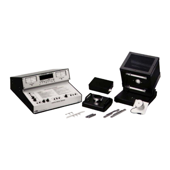
Page 5: Equipment Description
2.0 EQUIPMENT DESCRIPTION General The Model 406D Static Decay Meter shown in Figure 2.1-1 is designed to test the static dissipative characteristics of material by measuring the time required for a charged test sample to discharge to a known, predetermined cutoff level. - Page 6 Front panel indicator lights indicate the cutoff threshold selected, operating state and on/off status of the high voltage. The sample is contained in a special Faraday Cage, which includes a patented Electrostatic Sensor (ETS Patent No. 3824454) that enables the system to make a true electrostatic (non-contact) measurement of the charge on the sample.
- Page 7 2.2.4 Operate Controls The unit has four operating states related to sample decay time measurement. Three of the four states, ZERO/STANDBY, CHARGE and TEST are operator controlled while the fourth state, TEST OVER is automatically programmed by the unit at the end of each decay time test. 2.2.4.1 ZERO/STBY This momentary push button switch, when activated, places the unit in the ZERO/STANDBY state.
- Page 8 2.2.4.3 TEST This momentary push button switch, when depressed, steps the system from the CHARGE state to the TEST state. Here, the shutter in the sensor of the Electrostatic Voltmeter is open, the High Voltage Power Supply is turned off, the discharge relay is closed, causing the charge on the sample to start to decrease, and the DECAY TIME counter is activated allowing the sample decay time to be measured.
- Page 9 2.2.7 AUTO MODE These controls provide for programming the unit in the AUTO mode and are functional only when the AUTO/MAN button is in the AUTO (down) position. 2.2.7.1.TESTS This 10-position rotary switch selects the number of tests to be conducted.
- Page 10 2.3.1.2.CHARGING VOLTAGE Meter This analog meter provides an indication of the high voltage output level of the charging Voltage Power Supply. It is used in conjunction with the High Voltage ADJUST control to set the CHARGING VOLTAGE output level. It is calibrated to read directly in kV.
- Page 11 Rear Panel The rear panel of the Model 406D is shown in Figure 2.4-1 and contains all the input and output connections for the system. Starting with Serial #877 a universal switching power supplies that operates from 90- 260VAC, 50/60Hz is used.
- Page 12 screwdriver or similar tool. Remove the VOLTAGE SELECTOR CARD and move the INDICATOR pin so that it lines up with the desired voltage designation on the cover. To change the fuse(s), loosen the Phillips head screw 2 turns, remove the fuse block by sliding up, then away from the Phillips screw.
-
Page 13: Operation
2.6.2 STM-1 (NOTE: Supplied with all 406 Models up to Serial #877) The System Test Module (STM-1) supplied with each Model 406D Static Decay Meter prior to Serial # 877 enables the user to check its operation against a stable, repeatable standard. The STM-1 uses electronic... -
Page 14: Manual Mode
STM-1, insert the banana plug fully into the banana jack. The STM-2 does not incorporate a plug.] STM-2 Magnetic Electrodes Figure 3.2-1: System Test Module in the Faraday Cage NOTE: The unit employs a safety interlock system which will prevent high voltages from being impressed on the test sample unless the Faraday Cage cover is positioned in the operate (cover down) position. - Page 15 Table 3.1 Cutoff Levels and Applicable Specifications CUTOFF CUTOFF APPLICABLE THRESHOLD VOLTAGE* SPECIFICATION 2500 Half Life NFPA Code 99 Mil-PRF-81705C, EIA & ESDA 541 * Nominal value. Actual cutoff is the percentage selected by the CUTTOFF selector. Ex: Accepted voltage is 4.5kV, cutoff is 450V. 3.
-
Page 16: Auto Mode
4.0 "Testing Hints and Other Tests". AUTO Mode In this mode, the Model 406D Static Decay Meter will conduct up to 9 measurement cycles automatically, including automatic zero calibration. This mode cannot be used with samples that have an initial or a residual charge. - Page 17 1. Select the Cutoff level by depressing the appropriate CUTOFF button. 2. Select the number of test cycles desired by setting the AUTO mode TESTS selector to the appropriate number (1-9). The selector should be set such that the number desired is opposite the pointer on the panel above the selector.
- Page 18 Faraday Cage or when the unit is on but tests are not being conducted. 6. Faraday Cage Safety Interlock System - The Model 406D contains a Safety Interlock System which is designed to prevent the Control Unit from producing a high voltage output under certain conditions.
- Page 19 sure NOT to rotate it since this will reduce the signal level. At the conclusion of the system test, return the FULL SCALE ADJUST control back to the NORM position. Calibrate the full scale using a 3x5” (80x127mm) foil stretched between the electrodes. If the sample is not flat, make sure it is static dissipative and adjust the FULL SCALE ADJUST for a full scale reading.
- Page 20 the test. In either case, the unit will go through the usual test sequence and will display a DECAY TIME reading that should be within ±0.05 seconds of the value indicated on the STM System Test Module. If the DECAY TIME reading is not within this tolerance, the unit may be out of calibration, or may not be functioning properly.
- Page 21 Figure 3.4-2: Clamp Electrodes 3.4.3 Loose Fill Electrodes Loose Fill Electrodes are used to test loose fill packing chips. Six chips are needed for each test sample array. The chips must be placed over the electrode points and rest on the shoulder as shown in Figure 3.4-3. This is necessary in order to make contact with the outer surface of the chip so that surface treated material will be properly tested.
- Page 22 Figure 3.4-4: I.C. Shipping Tube Electrodes 3.4.5 Small Sample Electrodes The standard ETS Model 406D Static Decay Meter is designed to test film, fabric and rigid samples having a nominal size of 3" x 5". However, the electrodes can accommodate a sample size down to 4.125" in length.
- Page 23 a. Rigid Sample b. Fabric Sample Figure 3.4-5: Small Sample Electrode 3.4.6 Nondestructive Sample Testing The Nondestructive Static Decay Test Fixture Model 806B shown in Figure 3.4-6 replaces the Faraday Cage. It enables the user to non- destructively test larger objects such as tote boxes, sheet material, work surfaces, molded parts, etc.
- Page 24 3.4.6.1 Installation The Model 806B connects directly to the Control Unit of the Model 406D in the same manner as the Faraday Cage. The sensor head is removed from the Faraday Cage by loosing the brass thumbscrew that retains the sensor in the clamp. The sensor is then plugged into the 3 banana plugs located on the top of the Fixture as shown in Figure 3.4-6.
- Page 25 must be taken into account when testing finished product that may have a large area or multiple sides such as a box or bin. To determine a Pass/Fail criteria first perform a standard static test of the material the product is made from. Then perform the nondestructive test on the product.
- Page 26 remove the initial charge, but it will not alter it’s ability to conduct or dissipate charge. Effects of Humidity Chemically treated antistatic materials are dependent on the relative humidity for effectiveness. Both topically treated and internally mixed antistatic materials draw moisture from the atmosphere to produce an electrostatically conductive layer on the surface.
- Page 27 Time Constant - τ Figure 4.5-1: Standard and Method 4046 Exponential Decay Curves Measuring Laminated Film The Model 406D is specifically designed to measure the static decay characteristics of homogeneous static dissipative material having a surface resistance between 10 and 10 Ohms.
-
Page 28: System Adjustments
5.0 SYSTEM ADJUSTMENTS The Model 406D Static Decay Meter, like all precision electronic instruments, should be returned to the factory once a year for calibration. However, due to heavy use or having been moved to another location the instrument may require some minor adjustments in the interim. - Page 29 Full Scale Adjustment The Sensor Head has been set at the factory and should not have to be re- adjusted under normal circumstances. Should it be necessary to re-set the spacing of the sensor head, the following procedure should be followed: 1.
-
Page 30: Warranty
6.0 WARRANTY Electro-Tech Systems, Inc. warrants its equipment, accessories and parts of its manufacture to be and remain free from defects in material and workmanship for a period of one (1) year from date of invoice. ETS will, at its discretion either replace or repair without charge, F.O.B. - Page 31 APPENDIX A Method 4046 Electrostatic Properties of Materials Scope This test is used to determine the electrostatic properties of materials in filmed and sheet form, by measuring the time required to induce a charge on the surface of the material, measure the intensity and polarity of the charge, as well as the time required for complete dissipation of the induced charge.
- Page 32 Conditioning Prior to testing, expose one-third of the specimens for 12 days in an oven uniformly maintained at 160º ±5º F; one-third of the specimens in a horizontal position for 24 hours under a continuous water shower; and one-third of the specimens in an atmosphere uniformly maintained at 73º...
- Page 33 Set chart speed at 0.5 inch/second. Turn on the recorder. Turn meter switch to plus or minus, depending on charge to be applied. Move “operate” switch to position and then close charging switch to apply 5kV to test specimen. When the meter needle stops rising, indicating the specimen has received its maximum charge, close the ground switch to remove the charge.
- Page 34 APPENDIX B National Fire Protection Association (NFPA) Code 99 – Standard for Health Care Facilities (1993): Paragraph 12-4.1.3.8 Reduction in Electrostatic Hazard Paragraph 4663 Antistatic sheeting, film and textiles shall meet the specific requirements of at least one of the following test methods when preconditioned at 50%, ±2% RH at 70º...
- Page 35 APPENDIX C (Applicable sections) Mil-PRF-81705D, – Barrier Materials, Flexible, Electrostatic Protective, Heat Sealable: Scope This specification covers opaque and transparent heat sealable, electrostatic free, flexible, barrier materials for the packaging of missiles, explosive powered and electro-sensitive devices, micro-circuits, semiconductors, thin film resistors, and associated airborne components.
Need help?
Do you have a question about the 406D and is the answer not in the manual?
Questions and answers