Advertisement
Quick Links
Advertisement

Related Manuals for Electro-Tech systems 863


Summary of Contents for Electro-Tech systems 863
- Page 1 RESISTANCE/CURRENT METER Model 863/6487 BASIC OPERATING INSTRUCTIONS 10/10...
-
Page 2: Important Safety Instructions
IMPORTANT SAFETY INSTRUCTIONS The equipment described in this Manual is designed and manufactured to operate within defined design limits. Any misuse may result in electric shock or fire. To prevent the equipment from being damaged, the following rules should be observed for installation, use and maintenance. Read the following safety instructions before operating the equipment. -
Page 3: Maintenance And Service
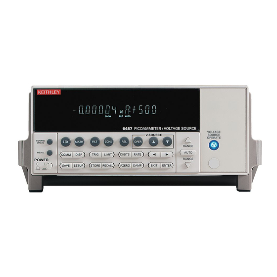
DO NOT OPERATE IN AREAS WITH HEAVY DUST: Operating the equipment in high dust conditions will cause deteriation in performance, system failure, or present a shock or fire hazard. Contact the factory for further instructions. DO NOT OPERATE IN AN EXPLOSIVE ATMOSPHERE: Operating the equipment in the presence of flammable gases or fumes hazard. - Page 4 The cable supplied has been specially adapted for direct interface with probes equipped with standard .162” banana jacks. The Model 863/6487 when used as a resistance meter measures over the resistance range of 0.8 ohms to 5 x 10 ohms (by V/I calculation).
- Page 5 (Blue warning light ON.) Connect the desired probe or test fixture to the Model 863/6487 using one of the setups shown in Figures 2.0–2,3,4 & 5. The cable schematic is shown Figure 2.0-1.
- Page 6 Ground Plane To external Ground connection Ground Plane is used when measuring insulative materials per ASTM D257 Insulating Plane Insulating Plane is used when measuring static dissipative materials per ESD S11.11 Figure 2.0-2: Surface Resistance/Resistivity...
- Page 7 Conductive Plane Insulated V-Source Plane Ground Figure 2.0-3: Volume Resistance/Resistivity Sense Not connected V-Source Red cable supplied with Model 850 Figure 2.0-4: Point-to-Point Resistance...
-
Page 8: Operation
Figure 2.0-5: 2-Point Resistance 2.0 OPERATION The Model 863/6487 is preprogrammed at ETS to measure resistance or resistivity with either a 10V, 100V or 500V test voltage by selecting one of the three user configurations, USR0, USR1 or USR2 respectively. - Page 9 4. To begin a test and take a reading, press the OPER push button. A blinking dot on the display will flash each time a sample is taken at an approximately six (6) second sampling rate that is preset by ETS. If another sampling rate is desired, refer to Section 4.2 for resetting the RATE value.
- Page 10 3.0 REPROGRAMMING The Model 863/487 is preprogrammed at the factory to enable the user to immediately place the instrument into service as a precision wide range resistance meter, meeting most common resistance and resistivity test specifications.
- Page 11 Figure 4.1–1: Source Voltage Adjust Sampling Rate (TRIGGER INTERVAL) The sampling rate (RATE) is set by ETS for the maximum sampling rate (NPLC:60.00) using the CONFIG RATE menu. This presents a more stable display when making high resistance measurements. The sampling rate is expressed in terms of the Number of Power Line Cycles (NPLCs).
-
Page 12: Default Settings
4. USER0 is selected as the power on default using the CONFIG SETUP menu. SAVING USER SETUPS To save a User Setup, configure the Model 863/6487 for the desired measurement application, then press SAVE and select the desired setup (0 = USR0, 1 = USR1, 2 = USR2) and press ENTER to complete the process.
Need help?
Do you have a question about the 863 and is the answer not in the manual?
Questions and answers