Advertisement
Table of Contents
Advertisement
Table of Contents

Related Manuals for Electro-Tech systems ASTM D 991 TEST FIXTURE


Summary of Contents for Electro-Tech systems ASTM D 991 TEST FIXTURE
- Page 1 ASTM D 991 TEST FIXTURE Model 831 Operating Manual 10/12...
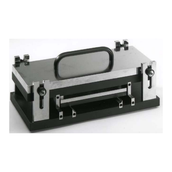
- Page 2 1.0 GENERAL DESCRIPTION The Model 831 D 991 Test Fixture, shown in Figure 1.0-1 is designed specifically to test material in accordance with ASTM D 991 – RUBBER PROPERTY - VOLUME RESISTIVELY ELECTRICALLY CONDUCTIVE ANTISTATIC PRODUCTS. Figure 1.0-1: Model 831 D 991 Test Fixture This method is used to evaluate the electrical behavior of rubber products (also applicable to other types of rigid and sheet material) that are used in applications such as safety, static charge accumulation and dissipation, current transmission,...
- Page 3 A’ B’ Voltage Source (Sense) Milliammeter Figure 1.0-2: Model 831 meter connections Using the following calculation from the D 991 test method, the volume resistivity of the material can be determined: ρ = Vwd where ρ = Volume resistively in Ohm-cm V = Potential difference across potential electrodes (B-B’) i = Current through specimen (A-A’) w = width of specimen (7.62cm)
- Page 4 The Fixture has a fixed mass based on the maximum measurement width of 4.0” (10.2cm) specimen width. Mass between current electrodes and specimen = 6.67 lb (3kg). Mass between potential electrodes and specimen = 1.34 lb (0.6kg) 2.0 SET-UP The Model 831 Test Fixture requires either a 4-pole resistance meter or individual instruments as shown in Figure 1.0-2.
- Page 5 At present, ESD materials are classified as follows: Conductive Dissipative Insulative ≥10 Surface <10 to <10 Ohms Volume same Materials with bulk resistance characteristics can also be classified by specifying its volume resistivity. Increasing or decreasing the thickness of the material will change the measured resistance of the part with a specified volume resistivity.
- Page 6 When performing measurements the following considerations should be taken into account: Verify instrument operation by performing calibration and operation checks per manufacturer recommendations. Verify test set-up by measuring a known sample with resistance in the1-10 MegOhm range. Read and record the ambient temperature and relative humidity. Verify that surfaces of the test specimen are clean and dry.
- Page 7 5.0 WARRANTY Electro-Tech Systems, Inc. warrants its equipment, accessories and parts of its manufacture to be and remain free from defects in material and workmanship for a period of one (1) year from date of invoice and will, at the discretion of Seller, either replace or repair without charge, F.O.B.
Need help?
Do you have a question about the ASTM D 991 TEST FIXTURE and is the answer not in the manual?
Questions and answers