Table of Contents
Advertisement
Quick Links
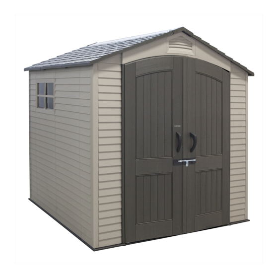
7' x 7'
OUTDOOR STORAGE SHED
MODEL 60231
BEFORE ASSEMBLY:
• Assemble on a level surface
• 3+ people recommended for setup
• Videos and help guides available
Scan the code below to see how it all comes
together.
http://go.lifetime.com/60231playlist
For Customer Service in mainland Europe:
E-mail: cs@lifetimeproducts.eu
TOOLS REQUIRED
QUESTIONS?
CONTACT LIFETIME CUSTOMER SERVICE:
Call: 1-800-225-3865
7:00 am-5:00 pm (Monday-Friday) MST
and 9:00 am-1:00 pm Saturday MST
Live Chat: www.lifetime.com
(click on "Ask An Expert" tab)
Video Instructions:
www.youtube.com/lifetimeproducts
ASSEMBLY INSTRUCTIONS
5/16" (8 mm) Wood Drill Bit
5/16" (8 mm) Masonry Drill Bit
1/2" x 4" x 7" Piece of Plastic
MODEL# AND PRODUCT ID
Model Number: 60231
Product ID:
TABLE OF CONTENTS
Icon Legend................................2
Warnings & Notices.....................3
Platform Construction..................4
Truss Assembly...........................9
Gable Assembly........................13
Door Assembly..........................16
Floor Assembly..........................27
Wall Assembly...........................31
Window Installation...................41
Door & Gable Installation...........44
Parts Identifi er..........................45
Roof Assembly..........................54
Door Alignment........................71
Shed Anchoring........................74
Latch Installation......................77
Cleaning & Care........................89
Registration...........................90
Warranty..............................91
(you will need both when contacting us)
Advertisement
Table of Contents

Related Manuals for Lifetime 60231


Summary of Contents for Lifetime 60231
-
Page 1: Table Of Contents
Cleaning & Care......89 Registration......90 1/2" x 4" x 7" Piece of Plastic Warranty......91 QUESTIONS? CONTACT LIFETIME CUSTOMER SERVICE: Live Chat: www.lifetime.com MODEL# AND PRODUCT ID Call: 1-800-225-3865 (you will need both when contacting us) (click on “Ask An Expert” tab) Model Number: 60231 7:00 am–5:00 pm (Monday–Friday) MST... -
Page 2: Icon Legend
ICON LEGEND • Indicates special heed should be taken when reading. • Indicates the parts to be used for a section. • Indicates no parts required for a specifi c section. • Indicates the hardware to be used for a section. •... -
Page 3: Warnings & Notices
WARNINGS & NOTICES English: • Failure to follow these warnings may result in serious injury or property damage and will void warranty. • To ensure safety, do not attempt to assemble this product without following the instructions carefully. • Consult all local building codes to verify if the shed requires a building permit. •... -
Page 4: Platform Construction
PLATFORM CONSTRUCTION • You must provide a platform on which to assemble your shed. Proper building permit documentation may be required in your neighborhood. Consult all local building codes prior to assembling the shed. Before beginning assembly, you must pour or construct a platform. There are two types: •... - Page 5 SECTION 1 (CONTINUED) CONCRETE REQUIRED 1 yd (0,77 m CONCRETE PLATFORM • The concrete should be approximately 4" (10,2 cm) thick. The actual dimensions of the shed, at its widest and longest points, are 84" x 84" (2,13 m x 2,13 m). Ensure you select a site that will accommodate these measurements.
- Page 6 SECTION 1 (CONTINUED) WOOD REQUIRED WOOD PLATFORM • The actual dimensions of the shed, at its widest and longest points, are 84" x 84" (2,13 m x 2,13 m). Ensure you select a site that will accommodate these measurements. The fl oor dimensions are a bit smaller than those of the roof; therefore, you will need to builld a level surface of 81 1/2"...
- Page 7 SECTION 1 (CONTINUED) TOOLS, PARTS, AND HARDWARE REQUIRED 2" x 4" x 81 1/2" (5,1 cm x 10,2 cm x 2,12 m) (x2) 2" x 4" x 80 3/8" (5,1 cm x 10,2 cm x 2,04 m) (x7) 16d 3" (16d x 7,62 cm) (x28) 1.2.1 WOOD PLATFORM •...
- Page 8 SECTION 1 (CONTINUED) TOOLS, PARTS, AND HARDWARE REQUIRED 33 1/2" x 83 3/8" x 3/4" (85,1 cm x 2,12 m x 19,1 mm) (x1) 48" x 83 3/8" x 3/4" (1,22 m x 2,12 m x 19,1 mm) (x1) 8d 1 1/2" (8d 3,81 cm) (x32) 1.2.3 •...
-
Page 9: Truss Assembly
TRUSS ASSEMBLY HARDWARE REQUIRED Hardware Bag ETC (x8) ADY (x8) ADJ (x4) CXK (x16) 8 1/4” 8 1/4" (20,96 cm) ADH (x2) PARTS REQUIRED / PIÈCES REQUISES / PIEZAS REQUERIDAS Metal Parts 43 1/4” 43 1/4" (1,10 m) AFH (x4) ETD (x2) 40"... - Page 10 • If you have trouble with this section, follow the code below to view a video on the assembly for this section. http://go.lifetime.com/7truss • Align the holes in a Connector (ETD) with those in the ends of the Truss Channels (AFH).
- Page 11 SECTION 2 (CONTINUED) TOOLS AND HARDWARE REQUIRED ETC (x8) ADY (x8) CXK (x16) • Align the holes in a Truss Brace (AFG) with those in • Secure the Connector to the Truss Gutter the Truss Gutter Channels. Channels using the hardware included. ETC (x4) CXK (x4) •...
- Page 12 SECTION 2 (CONTINUED) TOOLS AND HARDWARE REQUIRED 3/8 in/po (10 mm) 7/16 in/po (11 mm) (x2) 8 1/4” 8 1/4 in/po (20,96 cm) ADH (x2) ADJ (x4) • Slide a Truss Rod (ADH) through the holes in the Truss Brace and Connector. Secure with two Cap Nuts (ADJ). Lay Truss fl...
-
Page 13: Gable Assembly
GABLE ASSEMBLY HARDWARE REQUIRED Hardware Bag ADV (x6) ADZ (x3) PARTS REQUIRED Metal Parts 54 3/8” 54 3/8" (1,38 m) AFE (x1) Plastic Parts AGH (x1) AGF (x1) AGI (x1) TOOLS REQUIRED... - Page 14 • If you have trouble with this section, follow the code below Entry Gable (AGF). to view a video on the assembly in this section. • The fl at holes face away from the Gable. http://go.lifetime.com/gableassembly7 • The fl at hole faces downward. • Secure with the hardware included.
- Page 15 SECTION 3 (CONTINUED) TOOLS AND HARDWARE REQUIRED ADZ (x3) • Align the holes in the Left (AGH) and Right (AGI) Rear Gable Halves. • Secure the two together with three (3) Screws (ADZ).
-
Page 16: Door Assembly
LEFT DOOR ASSEMBLY HARDWARE REQUIRED Hardware Bag ADW (x1) CHK (x5) BYZ (x2) ARA (x1) AEE (x3) BBH (x1) DGR (x1) (Bottom) DGS (x1) (Top) PARTS REQUIRED Metal Parts 77 in/po (1,96 m) CHH (x1) 75 in/po (1,91 m) CHI (x1) - Page 17 LEFT DOOR ASSEMBLY HARDWARE REQUIRED Plastic Parts BYS (x1) BYR (x1) AGO (x1) TOOLS REQUIRED...
- Page 18 • Slide a Hinge Tube (CHH) down into the hole in the to view a video on the assembly in this section. Left Door (AGO). http://go.lifetime.com/7leftdoor • Insert a Square Tube (CHI) into the square hole in the bottom of the Door until the...
- Page 19 SECTION 4 (CONTINUED) TOOLS AND HARDWARE REQUIRED CHK (x1) • Insert an End Cap (BBH) into the end of the Square Tube (CHI). Gently, fi nish inserting the Tube until it’s fl ush with the bottom of the Door. • Once the End Cap is fl ush with the bottom of the Door, insert Self-Drilling/Self-Tapping Screw (CHK) into the Door Panel at the location shown to hold the Square Tube in place.
- Page 20 SECTION 4 (CONTINUED) TOOLS AND HARDWARE REQUIRED ARA (x1) • Drill two holes at the top and bottom of the Door at the locations indicated.
- Page 21 SECTION 4 (CONTINUED) TOOLS AND HARDWARE REQUIRED CHK (x4) DGS (x1) (Top) DGR (x1) (Bottom) • Secure the two Deadbolts (DGR & DGS) to the top and bottom of the Door using the hardware provided. The Deadbolts should move freely. If they do not, loosen the Screws a tad. CHK (x2) CHK (x2)
- Page 22 SECTION 4 (CONTINUED) TOOLS AND HARDWARE REQUIRED ADW (x1) AEE (x3) BYS (x1) BYZ (x2) BYR (x1) • Attach the Handle pieces (BYR & BYS) using the hardware provided.
- Page 23 RIGHT DOOR ASSEMBLY HARDWARE REQUIRED Hardware Bag AEE (x1) BBH (x1) ADW (x1) CHK (x1) BYZ (x2) BBI (x1) PARTS REQUIRED Metal Parts 77 in/po (1,96 m) CHH (x1) 75 in/po (1,91 m) CHI (x1) Plastic Parts BYS (x1) AGZ (x1) BYR (x1) TOOLS REQUIRED ARA (x1)
- Page 24 • Slide a Hinge Tube (CHH) down into the hole in the to view a video on the assembly in this section. Right Door (AGZ). http://go.lifetime.com/rightdoorassembly7 • Insert a Square Tube (CHI) into the square hole in the bottom of the Door until the end hangs out about 1/2” (12 mm).
- Page 25 SECTION 5 (CONTINUED) TOOLS AND HARDWARE REQUIRED ARA (x1) BBH (x1) • Insert an End Cap (BBH) into the end of the Square Tube (CHI). Gently, fi nish inserting the Tube until it’s fl ush with the bottom of the Door. •...
- Page 26 SECTION 5 (CONTINUED) TOOLS AND HARDWARE REQUIRED BYZ (x2) ADW (x1) BYS (x1) CHK (x1) BBI (x1) AEE (x1) BYR (x1) • Once the End Cap is fl ush with the bottom of the Door, insert Self-Drilling/Self-Tapping Screw (CHK) into the Door Panel at the location shown to hold the Square Tube in place.
-
Page 27: Floor Assembly
FLOOR ASSEMBLY HARDWARE REQUIRED Hardware Bag ADC (x1) BQC (x8) AHO (x2) Note: These Screws do not anchor the Floor; they only hold the Panels together. PARTS REQUIRED Plastic Parts AFX (x1) AGR (x2) TOOLS REQUIRED... - Page 28 Outer Floor Panel (AGR). The tabs interlock. Lay Panel down fl at. http://go.lifetime.com/rightdoorassembly7 45° • Attach an Outer Floor Panel (AGR) to the Inner Floor Panel.
- Page 29 SECTION 6 (CONTINUED) TOOLS AND HARDWARE REQUIRED AHO (x2) • Decide on which end you would like to install your Doors. Insert Bushings (AHO) through the holes in the Floor. The slit in the Bushing should face the front of the shed.
- Page 30 SECTION 6 (CONTINUED) TOOLS AND HARDWARE REQUIRED BQC (x8) • Insert the Screws (BQC) through the divots in the Floor Panels and into the tabs of the adjacent Floor Panels. (The divots are near the seams of the Floor Panels.) These Screws do not anchor the Floor; they only hold the Panels together.
-
Page 31: Wall Assembly
WALL ASSEMBLY HARDWARE REQUIRED Hardware Bag ADV (x6) ADZ (x74) PARTS REQUIRED Metal Parts 49 in/po (1,25 m) BXT (x1) 67 3/4 in/po (1,72 m) AFM (x5) 78 3/8” 78 3/8 in/po (1,99 m) BXX (x1) Plastic Parts AHD (x5) AHH (x1) AGL (x4) TOOLS REQUIRED... - Page 32 • If you have trouble with this section, follow the code below to • Attach a Wall Support Channel (AFM) to a Wall Panel view a video on the assembly in this section. (AHD) using fi ve (5) Screws (ADZ). Repeat this step for all Wall Panels. http://go.lifetime.com/7wall...
- Page 33 SECTION 7 (CONTINUED) TOOLS AND HARDWARE REQUIRED ADZ (x4) • Attach a Wall Support Channel (BXT) to the Window Wall Panel (AHH) using fi ve (4) Screws (ADZ).
- Page 34 SECTION 7 (CONTINUED) TOOLS AND HARDWARE REQUIRED • Insert the two left-most tabs at the bottom of the Corner Panel (AGL) into the two right-most slots along the front edge of the Floor. • Slide the Corner Panel to the left. Bend the Corner Panel.
- Page 35 SECTION 7 (CONTINUED) TOOLS AND HARDWARE REQUIRED (EUF) • Pull down on the Panel to insert the remaining tabs. To help with insertion, place the Plastic Block (EUF) under the Floor Panel directly under the tab being inserted. You should hear a “click” when the tab pops into place. Repeat this step for the second tab.
- Page 36 SECTION 7 (CONTINUED) TOOLS AND HARDWARE REQUIRED ADZ (x10) • Insert the tabs of two (2) Wall Panels (AHD) into the slots along the right edge of the Floor. Slide the Panels toward the Corner Panel. Secure the Panels to one another using fi ve (5) Screws (ADZ) for each Panel.
- Page 37 SECTION 7 (CONTINUED) TOOLS AND HARDWARE REQUIRED (EUF) ADZ (x15) • Attach this Corner Panel in the same manner you did the previous Corner Panel. • Insert the tabs of two (2) Wall Panels (AHD) into the slots along the rear edge of the Floor. Slide the Panels toward the Corner Panel.
- Page 38 SECTION 7 (CONTINUED) TOOLS AND HARDWARE REQUIRED (EUF) ADZ (x15) • Attach this Corner Panel in the same manner you did the previous Corner Panel. 7.10 • Insert the tabs of two (2) Wall Panels (AHH & AHD) into the slots along the left edge of the Floor.
- Page 39 SECTION 7 (CONTINUED) TOOLS AND HARDWARE REQUIRED (EUF) ADZ (x5) 7.11 • Attach this Corner Panel in the same manner you did the previous Corner Panel.
- Page 40 SECTION 7 (CONTINUED) TOOLS AND HARDWARE REQUIRED ADV (x6) 7.12 • Use a hand screwdriver to attach the Wall Support Tube (BXX) to the top of the rear Wall Panels using six (6) Screws (ADV).
-
Page 41: Window Installation
WINDOW INSTALLATION HARDWARE REQUIRED Hardware Bag ADZ (x2) AIS (x1) PARTS REQUIRED Plastic Parts AHE (x1) TOOLS REQUIRED... - Page 42 • Peel off the protective backing from both sides of view a video on the assembly in this section. the Window Pane (AHE). http://go.lifetime.com/7window • With the curved edge at the top and facing toward you, slide the Window Pane down into the opening.
- Page 43 SECTION 8 (CONTINUED) TOOLS AND HARDWARE REQUIRED ADZ (x2) AIS (x1) • Attach the Latch (AIS) at the top left corner of the Window. The Latch should move freely.
-
Page 44: Door & Gable Installation
DOOR & ENTRY GABLE INSTALLATION HARDWARE REQUIRED Hardware Bag BFY (x5) ADX (x2) AHP (x2) ADJ (x5) ADZ (x11) BXZ (x16) Plastic BYM (x1) PARTS REQUIRED Metal Parts 70 7/8" 70 7/8" (1,80 m) BYA (x1) 72 3/8” 72 3/8" (1,84 m) BYB (x1) Plastic Parts AGF (x1) -
Page 45: Parts Identifier
PARTS IDENTIFIER CONTENTS OF BOX 1 AGR (x2) AFX (x1) AGQ (x2) AHE (x1) AGL (x1) AHD (x5) AHH (x1) CONTENTS OF SMALL PARTS BOX ETD (x2) BYS (x2) EUG (x4) BYW (x2) EUF (x1) BYR (x2) BYX (x4) 26 11/16” 26 11/16"... - Page 46 PARTS IDENTIFIER BLISTER PACKS CONTENTS OF BOX 2 AGQ (x4) AGL (x3) AGO (x1) AGZ (x1) BYV (x1) AGF (x1) AGH (x1) AGI (x1)
- Page 47 PARTS IDENTIFIER CONTENTS METAL KIT 40" (1,02 m) AFG (x2) 43 1/4” 43 1/4" (1,10 m) AFH (x4) 67 3/4" (1,72 m) AFM (x5) 78 3/8” 78 3/8" (1,99 m) BXX (x1) 54 3/8” 54 3/8" (1,38 m) AFE (x1) 70 7/8"...
- Page 48 PARTS IDENTIFIER THIS PAGE INTENTIONALLY LEFT BLANK...
- Page 49 Panel. The Curved edge curves toward the inside of the shed. Align the holes in the Jamb with those in the Corner Wall Panel. Secure the Jamb to the Panel the required hardware. The top hole does not require a Screw—yet. http://go.lifetime.com/7doorinstall • Curved edge...
- Page 50 SECTION 9 (CONTINUED) TOOLS AND HARDWARE REQUIRED 7/16 in/po (11 mm) BFY (x5) ADJ (x5) BXZ (x10) Plastic • Place the Left Door Jamb (BYA) onto the edge of the left, front Corner Wall Panel. The Curved edge curves toward the outside of the shed.
- Page 51 SECTION 9 (CONTINUED) TOOLS AND HARDWARE REQUIRED AHP (x2) • Pull the Hinge Tube down out of the Door about six inches. Align the hole at the bottom of the Hinge Tube with the slit in the Bushing, and insert the Tube. Insert a Cotter Pin (AHP) and bend the ends. Repeat this step for the Right Door.
- Page 52 SECTION 9 (CONTINUED) TOOLS AND HARDWARE REQUIRED ADZ (x5) • Slide the holes in the Entry Gable down over the two Hinge Tubes. • Secure the Entry Gable to the shed using fi ve (5) Screws (ADZ). ADZ (x5)
- Page 53 SECTION 9 (CONTINUED) TOOLS AND HARDWARE REQUIRED BYM (x1) ADX (x2) • Attach the Strike Plate (BYM) to the Floor as shown.
-
Page 54: Roof Assembly
ROOF ASSEMBLY HARDWARE REQUIRED Hardware Bag ADV (x24) ADZ (x86) BYT (x16) PARTS REQUIRED Metal Parts 26 11/16” 26 11/16" (67,8 cm) BYY (x6) (x2) Plastic Parts BYV (x1) BYW (x2) AGQ (x6) BYX (x4) (x1) TOOLS REQUIRED... - Page 55 TOOLS AND HARDWARE REQUIRED • If you have trouble with this section, follow the code below to view a video on the assembly in this section. http://go.lifetime.com/7roofassembly 10.1 • Insert a Support Tube (BYY) into the notches of a Roof Support Panel (AGQ). Repeat this step for all Roof Panels.
- Page 56 SECTION 10 (CONTINUED) TOOLS AND HARDWARE REQUIRED ADZ (x3) BYT (x3) 10.2 • Set a Truss Assembly into the notches on the fi rst two opposite Wall Panels. Set a Roof Panel onto the Gable, Wall Panel, and Truss Assembly. 10.3 •...
- Page 57 SECTION 10 (CONTINUED) TOOLS AND HARDWARE REQUIRED ADZ (x5) ADV (x4) BYT (x1) 10.4 • Orient the bottom-most Clip (BYT) as shown in this image, and insert it into the location indicated. 10.5 • Insert four (4) long Screws (ADV) along the top edge of the Wall Panel and four (4) short Screws (ADZ) along the Truss as shown.
- Page 58 SECTION 10 (CONTINUED) TOOLS AND HARDWARE REQUIRED ADZ (x4) BYT (x4) 10.6 • Orient the Clips (BYT) as shown in this image, and insert them in the locations indicated. • See Step 10.7. 10.7 • Orient the Clip (BYT) as shown in this image, and insert them in the location indicated.
- Page 59 SECTION 10 (CONTINUED) TOOLS AND HARDWARE REQUIRED ADZ (x4) ADV (x4) 10.8 • Insert four (4) long Screws (ADV) along the top edge of the Wall Panel and four (4) short Screws (ADZ) along the Truss as shown. 10.9 • Set a Truss Assembly into the notches on the second two opposite Wall Panels. Set a Roof Panel onto the Gable, Wall Panel, and Truss Assembly.
- Page 60 SECTION 10 (CONTINUED) TOOLS AND HARDWARE REQUIRED ADZ (x8) ADV (x4) 10.10 • Set a Roof Panel onto the Gable, Wall Panel, and Truss Assembly, and secure it with the hardware shown. Only insert the long Screws (ADV) along the top edge of the Wall Panel. ADZ (x8) ADV (x4)
- Page 61 SECTION 10 (CONTINUED) TOOLS AND HARDWARE REQUIRED ADZ (x8) ADV (x4) 10.11 • Repeat the last step for the opposite Roof Panel. Only insert the long Screws (ADV) along the top edge of the Wall Panel. ADZ (x8) ADV (x4)
- Page 62 SECTION 10 (CONTINUED) TOOLS AND HARDWARE REQUIRED ADZ (x12) 10.12 • Set the Rear Gable onto the back Wall Panels, and secure with twelve (12) Screws (ADZ).
- Page 63 SECTION 10 (CONTINUED) TOOLS AND HARDWARE REQUIRED ADZ (x4) BYT (x4) 10.13 • Set the Roof Panel onto the Gable, Wall Panel, and Truss Assembly. Orient the Clips (BYT) as shown in this image, and insert them in the locations indicated.
- Page 64 SECTION 10 (CONTINUED) TOOLS AND HARDWARE REQUIRED ADZ (x4) ADV (x4) 10.14 • Insert four (4) long Screws (ADV) along the top edge of the Wall Panel and four (4) short Screws (ADZ) along the Truss as shown. Only insert the long Screws (ADV) along the top edge of the Wall Panel.
- Page 65 SECTION 10 (CONTINUED) TOOLS AND HARDWARE REQUIRED ADZ (x4) BYT (x4) 10.15 • Set the Roof Panel onto the Gable, Wall Panel, and Truss Assembly. Orient the Clips (BYT) as shown in this image, and insert them in the locations indicated.
- Page 66 SECTION 10 (CONTINUED) TOOLS AND HARDWARE REQUIRED ADZ (x4) ADV (x4) 10.16 • Insert four (4) long Screws (ADV) along the top edge of the Wall Panel and four (4) short Screws (ADZ) along the Truss as shown. Only insert the long Screws (ADV) along the top edge of the Wall Panel.
- Page 67 SECTION 10 (CONTINUED) TOOLS AND HARDWARE REQUIRED ADZ (x2) 10.17 • Insert two (2) pieces of Foam (BYX) into each End Cap (BYW) as shown. There are two end Caps. 10.18 • Connect the End Cap to the outside of the shed using two (2) Screws (ADZ).
- Page 68 SECTION 10 (CONTINUED) TOOLS AND HARDWARE REQUIRED ADZ (x2) 10.19 • Connect the End Cap to the inside of the shed using two (2) Screws (ADZ). 10.20 • Slide the Skylight (BYV) onto the top of the shed and underneath the End Cap. The end of the Skylight should touch the inside wall of the End Cap.
- Page 69 SECTION 10 (CONTINUED) TOOLS AND HARDWARE REQUIRED ADZ (x18) 10.21 • Connect the Skylight to the Roof Panels using eighteen (18) Screws (ADZ). ADZ (x9) ADZ (x9)
- Page 70 SECTION 10 (CONTINUED) TOOLS AND HARDWARE REQUIRED ADZ (x4) 10.22 • Connect the End Cap to the outside of the shed using two (2) Screws (ADZ). 10.23 • Connect the End Cap to the inside of the shed using two (2) Screws (ADZ).
-
Page 71: Door Alignment
DOOR ALIGNMENT HARDWARE REQUIRED Hardware Bag PARTS REQUIRED Plastic Parts EUG (x4) TOOLS REQUIRED... - Page 72 EUG (x4) • If you have trouble with this section, follow the code below to view a video on the assembly in this section. http://go.lifetime.com/dooralignment7 11.1 • If the Doors are not level, follow the steps on the next page to even them out.
- Page 73 SECTION 11 (CONTINUED) TOOLS AND HARDWARE REQUIRED EUG (x4) 11.2 • If the Left Door is higher, follow this step. Fig. 2 Fig. 3 Fig. 1 11.3 • If the Right Door is higher, follow this step. Fig. 3 Fig. 1 Fig.
-
Page 74: Shed Anchoring
SHED ANCHORING HARDWARE REQUIRED NO HARDWARE INCLUDED FOR THIS SECTION PARTS REQUIRED NO PARTS REQUIRED FOR THIS SECTION TOOLS REQUIRED 5/16" (8 mm) Wood Drill Bit 5/16" (8 mm) Masonry Drill Bit... - Page 75 SECTION 12 (CONTINUED) TOOLS AND HARDWARE REQUIRED 5/16" (8 mm) 12.1 • To anchor your shed, you must purchase the correct anchoring hardware. For a concrete platform, we recommend using a hammer drill, 5/16" (8 mm) masonry bit, four (4) 3/8" x 2" (10 mm x 5 cm) Concrete Screws and four (4) 3/8"...
- Page 76 SECTION 12 (CONTINUED) TOOLS AND HARDWARE REQUIRED 5/16" (8 mm) 12.1 • To anchor your shed, you must purchase the correct anchoring hardware. For a wood-framed platform, we recommend using a drill, 5/16" (8 mm) drill bit, four (4) 3/8" x 1 1/2" (10 mm x 4 cm) Lag Screws and four (4) 3/8" x 1"...
-
Page 77: Latch Installation
LATCH INSTALLATION HARDWARE REQUIRED Hardware Bag ACA (x3) CHK (x2) ADX (x9) AAB (x3) AEE (x9) AEB (x3) CVW (x1) CVT (x1) CVU (x1) CVV (x1) CVR (x1) CVQ (x1) CVS (x1) TOOLS REQUIRED 7/16" (11 mm) - Page 78 CVT (x1) • If you have trouble with this section, follow the code below to view a video on the installation in this section. http://go.lifetime.com/doorlatchslider 13.1 • Only after following the anchoring instructions, attach the Left Latch Bracket (CVT) to the Left Door using the...
- Page 79 SECTION 13 (CONTINUED) TOOLS AND HARDWARE REQUIRED 7/16" (11 mm) CVW (x1) ACA (x2) CVU (x1) CVV (x1) AEB (x2) AAB (x2) 13.2 • Slide the Large Right Latch Bracket (CVU) and Small Right Latch Bracket (CVV) onto the Latch (CVW) as shown. 13.3 •...
- Page 80 SECTION 13 (CONTINUED) TOOLS AND HARDWARE REQUIRED CVQ (x1) 13.4 • Slide the Large Right Cover Plate (CVQ) up under the Latch Assembly and rotate the Latch downward to its locked position as shown.
- Page 81 SECTION 13 (CONTINUED) TOOLS AND HARDWARE REQUIRED AEE (x3) ADX (x3) 13.5 • Secure the Large Cover Plate to the Door as shown using the hardware provided. AEE (x3) ADX (x3)
- Page 82 SECTION 13 (CONTINUED) TOOLS AND HARDWARE REQUIRED CVR (x1) AEE (x3) ADX (x3) 13.6 • Slide the Small Right Cover Plate (CVR) down under the Latch Assembly, and secure the Cover Plate to the Door as shown using the hardware provided. AEE (x3) ADX (x3)
- Page 83 SECTION 13 (CONTINUED) TOOLS AND HARDWARE REQUIRED CHK (x1) 13.7 • Close both Doors and lock the Latch. Adjust the Left Latch Bracket so the Latch slides through freely. 13.8 • Insert one (1) Self-Drilling/Self-Tapping Screw (CHK) through the hole in the Left Latch Bracket to secure it in place.
- Page 84 SECTION 13 (CONTINUED) TOOLS AND HARDWARE REQUIRED 7/16" (11 mm) CVS (x1) 13.9 • Tighten the Nut to the Left Latch Bracket. 13.10 • Place Left Cover Plate (CVS) over the Left Latch Bracket.
- Page 85 SECTION 13 (CONTINUED) TOOLS AND HARDWARE REQUIRED ADX (x3) AEE (x3) CHK (x1) 13.11 • Secure the Left Cover Plate to the Door as shown using the hardware provided. ADX (x3) AEE (x3) 13.12 • Insert one (1) Self-Drilling/Self-Tapping Screw (CHK) through the hole in the Left Cover Plate to secure it in place.
- Page 86 NOTES...
- Page 87 NOTES...
- Page 88 NOTES...
-
Page 89: Cleaning & Care
Congratulations on your Lifetime ® product purchase. By following the instructions below, your new Lifetime product should provide you with years of service and enjoyment. The polyethylene panels are stain- and solvent-resistant. Most stains can be removed using a mild soap and a soft-bristled brush. -
Page 90: Registration
. And you can rest assured that Lifetime ® will not sell or provide your personal data to other third parties, or allow them to use your personal data for their own purposes. We invite you to read our privacy policy at www.lifetime.com REGISTER today! -
Page 91: Warranty
All merchandise is sold on this condition, and no representative of the company may waive or change this policy. 5. This product is not intended for institutional or commercial use; Lifetime Products, Inc. does not assume any liability for such use. Institutional or commercial use will void the warranty. - Page 92 ® ENHANCE YOUR LIFETIME PURCHASE BY ADDING ACCESSORIES OR OTHER GREAT PRODUCTS ® To purchase accessories or other Lifetime products, visit us at: www.lifetime.com Or call: 1-800-424-3865 7:00 am–5:00 pm (M–F) MST and 9:00 am–1:00 pm Saturday MST www.lifetime.com...
Need help?
Do you have a question about the 60231 and is the answer not in the manual?
Questions and answers