
Related Manuals for Symbol WSS 1000


Summary of Contents for Symbol WSS 1000
- Page 1 WSS 1000 About This Manual Table of Contents Index Copyright Feedback Product Reference Guide 70-16192-03 Revision A August 1999...
- Page 2 WSS 1000 Product Reference Guide 70-16192-03 Revision A August 1999...
- Page 3 The software is provided strictly on an “as is” basis. All software, including firmware, furnished to the user is on a licensed basis. Symbol grants to the user a non-transferable and non-exclusive license to use each software or firmware program delivered hereunder (licensed program).
-
Page 4: Table Of Contents
Documents Available from Symbol Technologies ........xi... - Page 5 Wearing the WSS 1000 System with the Ring Scanner .......
- Page 6 Assembling the WS 1200 Scanner..........5-9 Wearing the WSS 1000 System with the WS 1200 Scanner ......5-10 Chapter 6.
- Page 7 WSS 1000 Product Reference Guide Troubleshooting ............. . . 7-6 Start-up Failure .
- Page 8 Contents Renaming Files on Flash Disk ..........C-20 Index Tell Us What You Think...
- Page 9 WSS 1000 Product Reference Guide viii...
-
Page 10: About This Manual
About This Manual The WSS 1000 Product Reference Guide provides general information about the WSS 1000 wearable scanning computer system components and accessories for system administrators or programmers responsible for setting up the WSS 1000 system. Chapter Descriptions Topics covered in this manual are: •... -
Page 11: Notational Conventions
Notational Conventions The following conventions are used in this document: • "Operator" and "User" refer to anyone using an application on a WSS 1000 system. • "PC" refers to the IBM personal computer or compatible system that you are using to develop applications. -
Page 12: Related Publications
Related Publications The following is a list of documents and publications that you may find useful if you want to know more about the WSS 1000 or about the tools and utilities that are available for writing applications. Documents Available from Symbol Technologies •... -
Page 13: Service Information
Call the Support Center from a phone near the scanning equipment so that the service person can try to talk you through your problem. If the equipment is found to be working properly and the problem is symbol readability, the Support Center will request samples of your bar codes for analysis at our plant. - Page 14 About This Manual Australia Austria Symbol Technologies Pty. Ltd. Symbol Technologies Austria GmbH 432 St. Kilda Road Prinz-Eugen Strasse 70 Melbourne, Victoria 3004 Suite 3 1-800-672-906 (Inside Australia) 2.Haus, 5.Stock +61-3-9866-6044 (Outside Australia) 1040 Vienna, Austria 1-505-5794 (Inside Austria) +43-1-505-5794 (Outside Austria)
- Page 15 WSS 1000 Product Reference Guide Germany Italy Symbol Technologies GmbH Symbol Technologies Italia S.R.L. Waldstrasse 68 Via Cristoforo Columbo, 49 D-63128 Dietzenbach, Germany 20090 Trezzano S/N Navigilo 6074-49020 (Inside Germany) Milano, Italy +49-6074-49020 (Outside Germany) 2-484441 (Inside Italy) +39-02-484441 (Outside Italy)
-
Page 16: Warranty
This warranty is provided to the original owner only and is not transferable to any third party. It shall not apply to any product (i) which has been repaired or altered unless done or approved by Symbol, (ii) which has not been maintained in accordance with any operating or handling instructions supplied by... -
Page 17: General
WSS 1000 Product Reference Guide Symbol’s Customer Service organization offers an array of service plans, such as on-site, depot, or phone support, that can be implemented to meet customer’s special operational requirements and are available at a substantial discount during warranty period. -
Page 18: Chapter 1. Getting Started
LCD and keyboard backlighting is also provided. The WSS 1000 system can be worn on either the right or left arm. The WWC 1000 and scanners are easily removed from their mounts allowing for interchangeable use by other operators. -
Page 19: Parts Of The Wss 1000 System
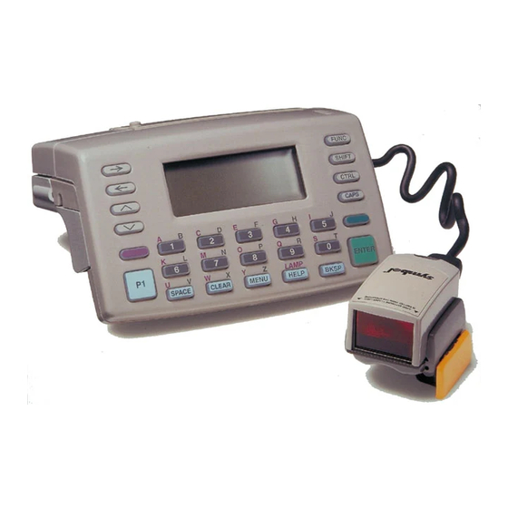
WSS 1000 Product Reference Guide Parts of the WSS 1000 System Wrist Computer (WWC 1000) Front View LCD Display Top View Speaker Keyboard Battery Latch Power Button Battery Charging Contacts Wrist Mount Lithium-Ion Battery Pack Snap-On Bar Rugged Boot Adjustable Straps... - Page 20 The WSS 1000 System RS 1 Scanner Front View Back View Mount Release Button Scan/Decode LED Scan Window Interface Connector Scan Trigger Ring Mount Adjustable Two-Finger Strap...
-
Page 21: Component Descriptions
WSS 1000 Product Reference Guide WS 1200 Scanner Scan LED Scanner Trigger Connector Connector Scan Window Back View Protective Cap Front/T op View Trigger Cable Scan Button Interface Cable Back View with Cables WS 1200 Mount Component Descriptions Wrist Computer Detaches from scanner and provides for minimum breakaway force as safety feature. - Page 22 The WSS 1000 System RS 1 Ring Mount Worn on either hand using a strap which wraps around both the index and middle fingers, preventing the scanner from rotating on the finger during use. Detaches from ring scanner, which then can be used by other operators wearing their own ring mounts.
-
Page 23: Radio And Network Options
WSS 1000 Product Reference Guide Radio and Network Options Spectrum One Network The WWC 1010 includes an internal radio frequency transmitter/receiver for use in a Symbol Spectrum One network. Spectrum24 Network The WWC 1040 includes an internal radio frequency transmitter/receiver for use in a Symbol Spectrum24 network. -
Page 24: Power Supply
Adapter cable (used with four-cradle power supply). Before You Use the WSS 1000 System Before using the WSS 1000 system for the first time, perform the following procedures: Install and Charge the Battery Charge the Lithium-Ion battery. The battery can be charged while in the wrist computer or separately in the cradle’s charging slot. - Page 25 WSS 1000 Product Reference Guide...
-
Page 26: Chapter 2. Cradle Setup And Battery Charging
To make the connection process easier, connect the power supply to the cradle before mounting. Single-Slot An optional metal bracket is available from Symbol as part of a kit for mounting the single- slot cradle to a wall. Contact a Symbol sales representative to order. - Page 27 WSS 1000 Product Reference Guide Four-Slot To wall mount the CS 1000 4-Slot Cradle: 1. Place the empty cradle on the wall where it is to be mounted. 2. Insert two #8 screws through the holes in the outer spare battery compartments (Figure 2-1).
-
Page 28: Connecting The Host And Cs 1000 4-Slot Cradle
Cradle Setup Connecting the Host and CS 1000 4-Slot Cradle To connect the CS 1000 4-Slot Cradle to a host computer for communications: 1. Plug the RS-232 serial cable’s DB-25 connector in the cradle’s communication port. The port is located on the back right-hand side of the single-slot cradle, and on the left side of the 4-slot cradle. - Page 29 WSS 1000 Product Reference Guide The four-slot cradle’s power port is in the center back; use power supply p/n 50-14000-052. Single-Slot Four-Slot Figure 2-3. Plugging Power Supply into Single-Slot and 4-Slot Cradles 4. Connect an adapter cable to the other end of the power supply.
-
Page 30: Connecting To Other Cradles
4. Repeat the above steps for any additional cradles you wish to connect. Battery Charging The WSS 1000’s primary power is provided by a 1200 mAh Lithium-Ion battery pack. Battery Life The approximate life of the battery pack between charges is a typical 8-hour shift @ 500 scans per hour. -
Page 31: When To Replace Or Recharge Batteries
WSS 1000 Product Reference Guide When to Replace or Recharge Batteries The WSS 1000 provides two types of indicators to notify you when battery power is running low: warning messages and modified cursors. These indicators may be changed or disabled by an application. -
Page 32: Replacing Batteries
Replace or recharge the primary batteries immediately upon receiving a dead battery message. Replacing Batteries To replace the Lithium-Ion battery pack (Symbol p/n 20-16228-02): 1. Power off the wrist computer. 2. Unlock and remove the battery compartment door. 3. Remove the spent battery pack. -
Page 33: Battery Charging
WSS 1000 Product Reference Guide Battery Charging Charging the Wrist Computer’s Battery To charge a Lithium-Ion battery in the CS 1000 Single-Slot or 4-Slot Cradle: 1. Verify that the cradle has power. 2. Slide the WWC 1000 in the cradle as shown in Figure 2-6 3. - Page 34 Cradle Setup 2. Lift the latch on the spare battery, and insert the battery in the cradle’s charging slot. The latch snaps into place when the battery is inserted. Figure 2-7. Inserting Spare Battery in Cradle 3. The spare battery is charged in approximately two hours, even if the WWC 1000 is charging at the same time.
- Page 35 WSS 1000 Product Reference Guide 2-10...
-
Page 36: Chapter 3. Batch And Spectrum One Initialization
Chapter 3 Batch and Spectrum One Initialization Communications For wrist computers used in a direct communications (batch) environment or a Spectrum One network environment, applications are transferred from a host computer over a communications line to the wrist computer. This procedure uses the SENDHEX program on the host computer and the Program Loader function (from Command Mode) on the WWC 1000. -
Page 37: Set Up For Initialization
WSS 1000 Product Reference Guide Set up for Initialization 1. Verify that the cradle is connected to the host PC. Refer to Chapter 2, Cradle Setup and Battery Charging. 2. Place the WWC 1000 in the cradle and power it off. -
Page 38: Initiate Host Communications Software On The Pc
Batch and Spectrum One Initialization Initiate Host Communications Software on the PC 1. Power on the host computer. 2. Start the communication program. 3. At a DOS prompt, enter the SENDHEX command: sendhex pgmname 38400 com2 where: SENDHEX is the command. pgmname is the application being loaded (.hex extension is optional). - Page 39 WSS 1000 Product Reference Guide c. Release <ENTER> and <FUNC>. The function selector screen displays: COMMAND MODE Select function Self Test 2. Scroll through the Command Mode options using UpArrow or DownArrow until "Program loader" displays. Press <ENTER>. 3. The WWC 1000 displays:...
-
Page 40: Starting Communications
Batch and Spectrum One Initialization Note: If 8 data bits is selected, the program selects "No parity" and skips the next step. 7. Parity. If 7 data bits is selected, the WWC 1000 displays: Comm Parameters Parity Press the first letter of a parity option (Even, Odd, None, Space, or Mark), or scroll using UpArrow and DownArrow and press <ENTER>... -
Page 41: Ending Communications
WSS 1000 Product Reference Guide If the host is not ready or the cable is not connected between the host PC and cradle, the wrist computer displays: Awaiting DSR 2. Press <ENTER> on the host computer. SENDHEX begins transmitting the program image. -
Page 42: Chapter 4. Spectrum24 Rf Terminal Setup
Chapter 4 ® Spectrum24 RF Terminal Setup Spectrum24 Terminals In Spectrum24 terminals, wireless connectivity is accomplished using standard communications protocols. Because they are standard, the protocols are generalized and take up considerably more space on the wrist computer’s NVM than was required for Spectrum ®... -
Page 43: Standard Spectrum24 Software
If your requirements are more advanced, refer to the Spectrum24 Network Development Kit documentation for more information on the Spectrum24 RF network, SLAODI.COM, the Symbol-provided ODI driver, and the configuration file setups required for various platforms. Boot Options & Internet Addressing... -
Page 44: Initializing The Wwc 1040
Spectrum24 RF Terminal Setup Initializing the WWC 1040 Note: This section covers specific settings required on first booting the WWC 1040, out of the box. For a complete review of the CFG24 screens, refer to Appendix C, Spectrum24 Network and Flash Disk Utilities. - Page 45 WSS 1000 Product Reference Guide On the WWC 1040 screen, the top and bottom lines of the menu are displayed, and the remaining lines are viewed by scrolling. In this menu, pressing <CLEAR> has the same effect as selecting Exit.
- Page 46 Spectrum24 RF Terminal Setup Table 4-1. Spectrum24 Configuration Parameters (Continued) Terminal Sleep Mode Determines whether radio is powered off after the wrist computer enters sleep mode due to inactivity. Refer to Appendix D for more information. The default value is “On”. Power Management If power management is set to PSP, the radio powers up only when there is traffic on the network.
- Page 47 WSS 1000 Product Reference Guide b. To change the Net Id, select Net Id from the CFG24 Menu. The Net Id screen is displayed. NET ID Enter Net Id(hex): BkSp, Clear, Enter Figure 4-3. Net Id Screen To change the current Net Id value, backspace over the current value and type a new value, in hexadecimal format, in the range 101 to 1FE.
- Page 48 Spectrum24 RF Terminal Setup d. Select Default Router from the main configuration menu. The Default Router screen is displayed. DEFAULT ROUTER Enter Default Router 157.235.93.178 BkSp, Clear, Enter Figure 4-5. Default Router Screen To change the current Default Router setting, backspace over the current value and type a new value, in decimal form.
- Page 49 WSS 1000 Product Reference Guide f. Select Diversity from the main configuration menu. The Diversity screen is displayed. DIVERSITY 2 antennas (Yes/No) ÇÈ,#Clear, Enter Figure 4-7. Diversity Screen ÇÈ To change the current Diversity setting, use the cursor keys to toggle between the settings “Yes”...
- Page 50 Spectrum24 RF Terminal Setup h. Select Boot Mode from the main configuration menu. The Boot Mode screen is displayed. BOOT MODE IP address from: Manual entry ÇÈ,#Clear, Enter Figure 4-9. Boot Mode Screen ÇÈ# To change the current boot mode, use the keys to toggle among the three settings: “Manual entry”, “BOOTP”, and “DHCP”.
-
Page 51: Initiating Network Connection
WSS 1000 Product Reference Guide The WWC 1040 displays the message: ...updating config data and proceeds with the initialization which writes the configuration values to a R/W non-volatile section of radio flash memory. Initiating Network Connection As the initialization continues, the wrist computer attempts to associate with the Spectrum24 AP using the default or newly entered Net Id. -
Page 52: Installing Application Software On Flash Disk
Spectrum24 RF Terminal Setup WWC 1040 Association with AP Successful If the association is successful, the wrist computer begins operating using the software files loaded on the flash disk. On first initialization, you probably don’t have applications loaded. Proceed with loading the applications as directed in Installing Application Software on Flash Disk on page 4-11. -
Page 53: Initiate Wwc 1040 Communications
WSS 1000 Product Reference Guide SENDHEX <hexfile> 384 [1|2]<ENTER> where: SENDHEX is the command <hexfile> is the hex file for the application being loaded. There may be other application hex files which load other software (e.g., STEP version 2.6.0 or greater, or TelNet Clients 3.0 or greater) to the flash disk. -
Page 54: Start Communications
A status of 0000 (all zeros) indicates a successful transfer. If the status is other than 0000, check the cable connections between the host PC and the cradle and repeat the process. If the problem persists, contact the Symbol Support Center for assistance. 4-13... -
Page 55: Updating System Software On Flash Disk
• if you are so directed by Symbol’s Technical Support staff. 1. Following the instructions for installing software on the flash disk (through step 5). Be sure, when entering the SENDHEX command on the PC, to issue the command from the directory where the hex file (LWP.HEX) is stored. -
Page 56: Multiple Applications On The Same Wrist Computer
Spectrum24 RF Terminal Setup Caution This removes the system software and all applications! Select 2, Use flash as-is, to update the flash while retaining the existing contents. 3. If you select 1, the WWC displays the message: Are You sure Y or N 4. - Page 57 WSS 1000 Product Reference Guide between applications requires re-initializing the wrist computer and selecting an alternative application when prompted. On warm boots, the wrist computer re-initializes and re-enters the same application that was selected before the re-initialization. On cold boots, if there are multiple applications available, an application selection menu is presented.
-
Page 58: Chapter 5. Assembling The Wss 1000 System
Chapter 5 Assembling the WSS 1000 System The WSS 1000 assembly consists of the WWC 1000 and mount together with a scanning component, the RS 1 ring scanner, or WS 1200 back-of-hand scanner. Assembling the WWC 1000 (Standard Unit) 1. Orient the cable on the WWC 1000 for right or left-handed operation. - Page 59 WSS 1000 Product Reference Guide 3. Place the WWC 1000 wrist computer onto the wrist mount, facing you. Be sure the mount is oriented so that the longer strap will be further up the forearm. 4. Snap the bar over the WWC 1000 using the snaps on either side of the mount. The straight part of the bar lies across the front of the WWC 1000, with the curved part in back.
-
Page 60: Assembling The Wwc 1000 (Rugged Boot Option)
Operating the WSS 1000 Assembling the WWC 1000 (Rugged Boot Option) When using the WSS 1000 in harsher conditions, a rugged boot mount may be ordered. To assemble the WWC 1000 with the rugged boot: 1. Orient the cable on the WWC 1000 for right or left-handed operation. - Page 61 WSS 1000 Product Reference Guide 4. Place the WWC 1000 wrist computer onto the wrist mount by sliding it into the protective sleeve. Figure 5-4. Sliding WWC 1000 into Sleeve 5. Snap the mount straps onto the WWC 1000 to secure.
-
Page 62: Assembling The Ring Scanner
Operating the WSS 1000 Assembling the Ring Scanner 1. Adjust the strap of the ring mount to fit your right or left index and middle fingers: a. Slip the mount onto your right or left index and middle fingers, oriented so the trigger is next to your thumb. - Page 63 WSS 1000 Product Reference Guide c. Slide the ring scanner backwards into the mount. Figure 5-8. Sliding the Ring Scanner into the Mount 3. Plug the cable connector from the WWC 1000 in the interface port on the back of the ring scanner, with the arrow on the top of the cable facing up.
-
Page 64: Wearing The Wss 1000 System With The Ring Scanner
Wearing the WSS 1000 System with the Ring Scanner To assemble the WSS 1000 system with the ring scanner on your arm and hand: 1. Slide the wrist mount on your arm, so that the longer strap is further up your arm. -
Page 65: Removing The Ring Scanner
WSS 1000 Product Reference Guide 4. Slide the ring mount and ring scanner on your right or left index and middle fingers with the trigger next to your thumb. Figure 5-12. Sliding Ring Mount and Scanner Onto Finger Removing the Ring Scanner To remove the ring scanner for use by another operator: 1. -
Page 66: Assembling The Ws 1200 Scanner
Assembling the WS 1200 Scanner The WS 1200’s mount can be used by both right and left-handed users. Note: Verify that the WSS 1000 has the correct data cable, shown below, for use with the WS 1200 scanner. Figure 5-14. WS 1200 Data Cable 1. -
Page 67: Wearing The Wss 1000 System With The Ws 1200 Scanner
WSS 1000 Product Reference Guide Figure 5-17. Placing WS 1200 onto Mount Wearing the WSS 1000 System with the WS 1200 Scanner 1. Slip the WS 1200 mount’s strap through the buckle as shown below to create a loose loop. -
Page 68: Chapter 6. Operating The Wss 1000
Operating the WSS 1000 4. Slide an appropriately sized o-ring onto your middle finger, or onto both your middle and ring fingers, and secure using the strap on the front of the mount. Figure 5-20. Attaching O-Ring 5. Pull the hand strap snug, then use the velcro to secure the strap. Place the lip on the front of the terminal mount over the velcro area on the scanner mount to secure the two units together. - Page 69 WSS 1000 Product Reference Guide 5-12...
-
Page 70: Power On And Off
Chapter 6 Operating the WSS 1000 Power On and Off Because the WWC 1000 is battery powered, it is important to save power whenever possible. The period of time that the wrist computer can be used before recharging or replacing the battery can be increased by turning the wrist computer off when not entering data. -
Page 71: Automatic Power
WSS 1000 Product Reference Guide Automatic Power A number of other events may turn a wrist computer on or off, depending on the application. Some of these are: Power On Via System Control The system powers on when a key other than the Power button is pressed. -
Page 72: Booting The Wwc 1000
Operating the WSS 1000 Booting the WWC 1000 Powering the WWC 1000 on does not boot the system or initialize the program or data. To initialize the WWC 1000, perform either a warm or cold boot. Warm Boot A warm boot resets the operating system while preserving the program and data on the RAM disk. -
Page 73: Cold-Boot Failure
WSS 1000 Product Reference Guide The wrist computer displays a copyright message, amount of RAM, and expanded memory. Other messages are displayed as well, depending on the system configuration. Cold-Boot Failure During a cold boot, the system briefly displays a status line for each driver as it loads in the... -
Page 74: Boot To Command Mode
Operating the WSS 1000 Boot to Command Mode Command Mode provides functions for: Performing a Program Download to transfer an application program from the host • system to the WWC 1000 (refer to Ending Communications on page 3-6). Running the Self-Test program to verify that the hardware is operating properly •... -
Page 75: Adjusting The Display
WSS 1000 Product Reference Guide Adjusting the Display Backlighting The WWC 1000’s backlight illuminates the display in dimly lit areas. The backlight can be turned on in two ways: Press <LAMP> (LeftAlpha and HELP). • Through the application (Interrupt 10h, Function 82h). -
Page 76: The Wwc 1000 Keyboard
Operating the WSS 1000 The WWC 1000 Keyboard The keyboard is used for entering data and issuing commands to the WWC 1000. Figure 6- illustrates the standard 27-key keyboard. The keys on the keyboard are distinguished as modifier keys and character keys. Because WWC 1000 keyboards have fewer keys than PC keyboards, each character key can produce more than the usual one or two characters. -
Page 77: Key Descriptions
WSS 1000 Product Reference Guide For example: Pressing the right or left <Alpha Shift> causes the numeric keys to produce the letters • listed above them. The left-hand Alpha Shift produces the letters in purple; the right- hand Alpha Shift produces the letters in green. -
Page 78: Keyboard State
Operating the WSS 1000 Table 6-1. Special Keys and Sequences (Continued) Key Name Description BKSP Following <Right Alpha> produces the same result as CLEAR (see above). MENU Defaults to F9, if not otherwise programmed by the application. Help key. Refer to... -
Page 79: Scanning
Note: Before scanning can occur, the application must implement routines to support bar code scanning. For information on scanning applications, refer to the Series 3000 ADK. Bar code types (with full autodiscrimination) supported by the WSS 1000 include: Code 3 of 9 (standard and full ASCII) •... -
Page 80: Scanning With The Ws 1200 Scanner
The long range version of the WS 1200 scanner uses an optional aiming dot to assist you in directing the scan beam. If Single Trigger Aim Mode is enabled by the software: 1. Power the WSS 1000 system and scanner on by pressing the trigger or the wrist computer’s power button. -
Page 81: Scanning Considerations
WSS 1000 Product Reference Guide Note: Scanner use depends on the application. The procedure for your scanner may differ. Table 6-2. LED Indications (Subject to Application Use) Message Green LED Red LED Successful Decode Scanning Scanner in Blink Mode Blinking... -
Page 82: Communications
Operating the WSS 1000 minimum element widths of bar code symbols. Refer to Appendix A for the RS 1 and WS 1200 decode zones. Communications Connecting Cable for Data Communications to a Host Computer 1. Plug serial cable (RS-232) into the communication port located on the right side of the back of the single-slot cradle, or on the left end of the 4-slot cradle. - Page 83 WSS 1000 Product Reference Guide 6-14...
-
Page 84: Chapter 7. Maintainance And Troubleshooting
Chapter 7 Maintainance and Troubleshooting Cleaning Wrist Computer To clean the wrist computer, use a clean, soft cloth dampened with a mild cleaner such as soap and water. Do not use abrasive paper, cloth, or abrasive/corrosive cleaners. Clean the keypad and scanner triggers, and wipe the display window with lens tissue. -
Page 85: Ws 1200 Scanner
WSS 1000 Product Reference Guide WS 1200 Scanner Wipe the scanner window periodically with a lens tissue or other material suitable for cleaning optical material, such as eyeglasses. Caution Do not pour, spray, or spill any liquid on the scanner. - Page 86 Maintaining the WSS 1000 3. Grip the exposed sides of the scanner and pull the scanner out of the cap. 4. Push the scanner into the back of the new cap so the ports appear through the back opening of the cap.
-
Page 87: Error Messages
WSS 1000 Product Reference Guide Error Messages If ERR3000 is loaded in the system configuration, the wrist computer displays the following messages to indicate error conditions that affect system performance. A message is usually accompanied by one or more beeps, after which the system returns to its previous status. -
Page 88: Communication Status Codes
Maintaining the WSS 1000 Communication Status Codes The program loader status code consists of four hexadecimal digits which indicate whether or not the transfer was successful, and if not, the source of the communications error. A status code of 0000 indicates success; any other code indicates failure. -
Page 89: Troubleshooting
WSS 1000 Product Reference Guide Troubleshooting Start-up Failure Problems are most frequently start-up failures. If cold booting the wrist computer does not start the application successfully, either the application, the system software, or the system is malfunctioning. If you can boot the system to command mode, try the following: Use Program Loader to download a new version of the software to NVM. -
Page 90: Spectrum24 Terminal
Maintaining the WSS 1000 Spectrum24 Terminal Typical initialization and operating problems and solutions for Spectrum24 terminals are provided in Table 7-3. Table 7-3. Troubleshooting Spectrum24 Terminals Problem Explanation/Action Out of range Terminal is out of the Access Point’s range. If you move the terminal during initialization, the terminal may be out of range of the AP and unable to complete the initialization process. -
Page 91: Self Test Function
Running the Self Test Access the Self Test function from the Command Mode menu: 1. Boot to command mode (refer to Chapter 6, Operating the WSS 1000 for boot sequences). 2. On the Command Mode screen, use the UpArrow or DownArrow to scroll through the options. -
Page 92: Keyboard Test
Maintaining the WSS 1000 Keyboard Test Keyboard testing can be performed while the wrist computer displays Config Screen 1 results. Test any keys except <Right Alpha Shift>. When you press a key, the corresponding scan code is displayed on the top row to the right of the test name. For the codes for each key on the 27-key keyboard, refer to the scan codes for the unmodified, right unmodified, and left unmodified keyboards. - Page 93 WSS 1000 Product Reference Guide Typical parameters are: 38400 bps 7 bit data Odd parity Xon/Xoff flow control Wrist Computer 1. Boot the wrist computer to Command Mode (refer to Boot to Command Mode on page 6-5 for the appropriate key sequence).
-
Page 94: Start Communications
Maintaining the WSS 1000 Set the range and press <ENTER>. 7. The wrist computer displays a range verification screen. For example: RAM 0000 3FFF NVM C839 DFFF None Correct? If the values are correct, press <ENTER>. If the values are not correct, press <CLEAR>... -
Page 95: End Communications
WSS 1000 Product Reference Guide Memory Transfer Sending: XXXX The display is updated for every 1024 bytes (1 KB) of memory. 4. When the transmission completes or aborts, the wrist computer displays the transmission status screen: Memory Transfer Status 0000 A status of 0000 (all zeros) indicates that the transfer was successful. -
Page 96: Appendix A Specifications
Appendix A Specifications Environmental Considerations The WSS 1000’s operating conditions are listed in Table A-1. Table A-1. Operating Specifications Operating Temperature -20° to 50°C (-4°F to 122°F) Storage Temperature -40° to 60°C (-40° to 140°F) The battery may be stored at -40° C for up to 72 hours. -
Page 97: Rs 1 Decode Zone
WSS 1000 Product Reference Guide RS 1 Decode Zone Note: Note: Typical performance at 68°F (20°C) on high quality symbols Note: Note: 25.4 12.7 Scanner 7.5 Mil 12.7 15 Mil 20 Mil 40 Mil 25.4 55 Mil In. Cm. 26 In. -
Page 98: Appendix Bwwc 1000 Keyboards
Appendix B WWC 1000 Keyboards Introduction The WWC 1000 wrist computer has a configurable 27-key keyboard. By combining keystrokes, the keyboard can emulate the full IBM-PC XT keyboard. This appendix provides the standard keyboard definitions and indicates how key codes are produced on the WWC 1000 wrist computer. -
Page 99: Keyboard Diagrams
WSS 1000 Product Reference Guide The character generated is a function of the key scan code and the keyboard state, as on a PC. The main difference is that the scan code generated by a key is also variable, determined by the keyboard state. - Page 100 Keyboards → FUNC ← CAPS CTRL ∨ CAPS LOCK RIGHT LAMP Figure B-2. Left Unmodified Keyboard → ALT STATE ← SHIFT NUM LOCK ∨ CAPS LOCK LEFT ENTER BKSP Figure B-3. Right Unmodified Keyboard...
- Page 101 WSS 1000 Product Reference Guide FUNC CTRL CAPS LOCK RIGHT LEFT & ENTER SPACE CLEAR MENU HELP BKSP Figure B-4. Shift Modified Keyboard FUNC CAPS LOCK SHIFT CAPS LOCK RIGHT LAMP Figure B-5. Shift Left Modified Keyboard...
- Page 102 Keyboards NUM LOCK CAPS LOCK LEFT > ENTER BKSP Figure B-6. Shift Right Modified Keyboard → ← SHIFT ∨ NUM LOCK RIGHT LEFT DARK CLEAR MENU HELP LIGHT Figure B-7. Function Modified Keyboard...
- Page 103 WSS 1000 Product Reference Guide → ← NUM LOCK FUNC ∨ NUM LOCK RIGHT ’ ‘ LAMP Figure B-8. Function Left Modified Keyboard → ← SHIFT NUM LOCK ∨ NUM LOCK LEFT HELP LAMP LIGHT Figure B-9. Function Right Modified Keyboard...
- Page 104 Keyboards NUM LOCK RIGHT LEFT SH-F1 SH-F2 SH-F3 SH-F4 SH-F5 SH-F6 SH-F7 SH-F8 SH-F9 SH-F10 DARK SH-F9 SH-F1 CLEAR LIGHT Figure B-10. Shift-Function Modified Keyboard NUM LOCK FUNC NUM LOCK < RIGHT “ SH-F10 LAMP Figure B-11. Shift-Function Left Modified Keyboard...
- Page 105 WSS 1000 Product Reference Guide NUM LOCK NUM LOCK LEFT SH-F1 LAMP LIGHT Figure B-12. Shift-Function Right Modified Keyboard...
-
Page 106: Appendix C Spectrum24 Network And Flash Disk Utilities
Appendix C Spectrum24 Network and Flash Disk Utilities Introduction Some supplemental utilities are provided for working with the flash disk in addition to the flash disk driver and utilities described in the Series 3000 ADK (refer to the section on FLASHDSK.SYS in the Device Driver chapter of the Series 3000 Application Programmer’s Reference Manual). -
Page 107: Cfg24
WSS 1000 Product Reference Guide CFG24 The CFG24 utility enables the terminal operator to configure radio communications parameters. This utility must be run after the radio driver loads because the configuration parameters are saved in the radio card’s flash memory, which is accessed using the radio driver services. - Page 108 Spectrum24 Network and Flash Disk Utilities Initially, CFG24 presents the main menu shown in Figure C-1. CONFIGURATOR 1.XX View config params Net Id Subnet Mask Default Router Terminal IP Address Diversity Terminal Sleep Mode Boot Mode Figure C-1. CFG24 Main Menu The current selectable option appears in reverse video.
- Page 109 WSS 1000 Product Reference Guide 2. Select Net Id from the CFG24 Menu. The Net Id screen is displayed. NET ID Enter Net Id(hex): BkSp, Clear, Enter Figure C-3. Net Id Screen The Net Id identifies the radio network and differentiates between different radio networks.
- Page 110 Spectrum24 Network and Flash Disk Utilities 4. Select Default Router from the main configuration menu. The Default Router screen is displayed. DEFAULT ROUTER Enter Default Router 157.235.93.178 BkSp, Clear, Enter Figure C-5. Default Router Screen The default router address is the address of the node where all packets going to remote networks are sent.
- Page 111 WSS 1000 Product Reference Guide To change the current Terminal IP Address, backspace over the current value and type a new value in decimal form. Each part of the four-part address must be in the range 0 to 255. Press <ENTER> to effect the change. Press <CLEAR> to exit without changes.
- Page 112 If boot mode is set to “DHCP” when the terminal is initialized, the process is the same as for BOOTP, except the Dynamic Host Configuration Protocol is used. Symbol’s BOOTP program accepts setting the following network parameters from the BOOTP and DHCP parameters:...
- Page 113 WSS 1000 Product Reference Guide ÇÈ To change the current boot mode setting, use the keys to toggle between the three valid settings. Press <ENTER> to effect the change. Press <CLEAR> to exit without changes. 9. Select Power Management from the main configuration menu. The Power Management screen is displayed.
-
Page 114: Bootp
Spectrum24 Network and Flash Disk Utilities BOOTP The BOOTP program gets the IP address and sets up communications parameters for use by other parts of the system. How the program works depends on which boot mode setting was selected in CFG24, as follows: •... -
Page 115: Output
WSS 1000 Product Reference Guide Output The following parameters in the radio flash save area are updated if changed by a BOOTP or DHCP process: Sub-network Mask BOOTP or DHCP response may change the sub-network mask. If no change is received from the BOOTP or DHCP response, uses the default of 255.0.0.0. -
Page 116: Stat24
Spectrum24 Network and Flash Disk Utilities STAT24 STAT24 is a Terminate and Stay Resident (TSR) program used to provide the status of the radio connection. It can also be used to check for RF association and alternate actions in batch files depending on the association status. This utility is used mainly to check for associations with an AP when RF difficulties are experienced. - Page 117 WSS 1000 Product Reference Guide The fields in Figure C-11 are interpreted as follows: Line 1 Title and version number of STAT24. Line 2 The terminal’s IEEE address. Line 3 The version and date of the adapter firmware. Line 4 The IEEE (MAC) address of the Access Point the terminal is associated with.
-
Page 118: Diag24
Spectrum24 Network and Flash Disk Utilities DIAG24 DIAG24 is used in two situations: • As a connectivity tool, using a ping that is not re-tried on transmission errors. This test is intrusive as pings are sent as fast as possible. •... - Page 119 WSS 1000 Product Reference Guide The set-up menus that follow are the same as the mode selected from the DIAG24 menu. The title line of the first screen indicates the selected test mode: AP PING TEST for selection 1; FIELD DIAGNOSTICS for selection 2.
- Page 120 Spectrum24 Network and Flash Disk Utilities 5. Select the ping message size by pressing the corresponding number, and advance to the next screen. Press Q or <CLEAR> to return to the main menu. <Test Mode> NUMBER OF PINGS 1. 100 pings 2.
-
Page 121: Ping Tests
WSS 1000 Product Reference Guide Ping Tests During an AP ping test, the following screen is displayed and continuously updated. AP PING TEST A Cnt Err AP RS 04 36 04 36 04 36 TMO 04 36 04 36 Press ‘Q’ to Quit Figure C-17. -
Page 122: Field Diagnostics
Spectrum24 Network and Flash Disk Utilities Figure C-18, the first detail line reads “*6*2...” showing that the real values for the counters in the second and subsequent detail lines are 600, 057, and 2,002. Press <Q> or <CLEAR> to terminate the test and return to the DIAG24 menu. AP PING TEST Total secs = 7.4 Pings = 100... - Page 123 WSS 1000 Product Reference Guide When the test stops, a summary screen is displayed. FIELD DIAGNOSTICS Total secs = 8.2 Pings = 100 Packet size = 512 Retries = 6 Timeouts = 4 [R]epeat or [Q]uit Figure C-21. Field Diagnostics Summary Screen Press <Q>...
-
Page 124: Flash.bat
Spectrum24 Network and Flash Disk Utilities FLASH.BAT The FLASH.BAT utility facilitates copying files to and deleting files from flash disk, and renaming files on the disk. The batch file switches to write mode on flash disk and restores read-only mode after the operation. Deleting Files from Flash Disk To delete files, use the command: FLASH DEL <filename>... - Page 125 WSS 1000 Product Reference Guide Note: In the second example, the E: drive must be mentioned on the first command parameter, but is assumed on the second parameter and must NOT be mentioned. Renaming Files on Flash Disk To rename files on the flash disk, use the command: FLASH REN \<OLD FILE NAME>...
- Page 126 Code 93 ..... . . 6-10 from Symbol ....C-7 Discrete 2 of 5 .
- Page 127 ......7-1 disconnecting RS 1 cable to WSS 1000 ..5-8 ring carrier ..... 7-1 display ring scanner .
- Page 128 Index external event power on ....6-2 DHCP ......4-2 manual entry .
- Page 129 WSS 1000 Product Reference Guide status codes ..... 7-5 maintenance cleaning ......7-1 memory transfer .
- Page 130 Spectrum One symbol support center ....xii loading applications ....3-1 system software Spectrum One radio network .
- Page 131 WSS 1000 Product Reference Guide mount ......1-5 parts of WS 1200 scanner ... 1-4 UBC 1000 .
- Page 132 We’d like to know what you think about this manual. Please take a moment to fill out this questionnaire and fax this form to: (516) 738-3318, or mail to: Symbol Technologies, Inc. One Symbol Plaza M/S B-4 Holtsville, NY 11742-1300 Attn: Technical Publications Manager IMPORTANT: If you need product support, please call the appropriate customer support number provided.
- Page 133 70-16192-03 Revision A — August 1999 Symbol Technologies, Inc. One Symbol Plaza, Holtsville N.Y. 11742...
Need help?
Do you have a question about the WSS 1000 and is the answer not in the manual?
Questions and answers