
Related Manuals for Hi-Link HLK-LD015-5G


Summary of Contents for Hi-Link HLK-LD015-5G
- Page 1 Shenzhen Hi-Link Electronic Co., Ltd. HLK-LD015-5G Radar Module User Manual Version: V1.0 Date: Jun.6th.2020 All rights reserved © Shenzhen Hi-Link Electronic Co.Ltd...
-
Page 2: Table Of Contents
Contents 1. BRIEF INTRODUCTION ............................1 2. MODULE PICTURE..............................1 3. INPUT AND OUTPUT INTERFACE........................2 4. MECHANICAL DIMENSIONS..........................2 5. ELECTRICAL PARAMETERS..........................3 6. SENSING TIME AND SENSING DISTANCE ADJUSTMENT................3 7. PHOTOSENSITIVE DETECTION......................... 4 8. MODULE POWER-ON SEQUENCE DIAGRAM....................4 9. SCHEMATIC DIAGRAM OF DETECTION RANGE...................5 APPENDIX A DOCUMENT REVISION HISTORY....................6... -
Page 3: Brief Introduction
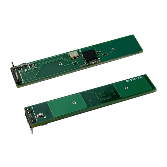
User Manual 1. Brief Introduction HLK-LD015-5G is a miniaturized 5.8G radar sensor launched by Hi-Link. The module size is 46*8mm. The module fully integrates 5.8G microwave circuit, intermediate frequency amplifier circuit and signal processor, with high integration and good production consistency. The peripheral is matched with a miniaturized planar antenna, which greatly reduces the overall size while ensuring the performance of the sensor. -
Page 4: Input And Output Interface
HLK-LD015-5G User Manual 3. Input and Output Interface The module reserves 5 pin holes with a PIN distance of 1.2mm. The three PINs VCC, GND and OUT are used by default. If parameters such as distance and delay time need to be modified, they can be flexibly configured through the serial port RX and TX. -
Page 5: Electrical Parameters
°C 6. Sensing time and sensing distance adjustment HLK-LD015-5G requires 3 pins by default, namely VCC, GND and OUT. At this time, the induction delay and induction distance are fixed values. If you need to adjust the induction delay and induction distance and other related parameters, you need to add 2 pins, RX and TX, on the hardware as shown in Figure 3. -
Page 6: Photosensitive Detection
HLK-LD015-5G User Manual Add Serial port or I/O port Figure 3. PIN Foot of Parameter Adjustment 7. Photosensitive detection The module supports photosensitive detection, but photosensitivity can be optional. If photosensitive function is required, a photosensitive diode and regulation resistor can be added to the position shown in Figure 4. -
Page 7: Schematic Diagram Of Detection Range
Figure 6. Schematic diagram of HLK-LD015-5G detection range (unit: m) Precautions When installing, avoid metal shells or parts on the front of the antenna to avoid shielding the signal. -
Page 8: Appendix A Document Revision History
HLK-LD015-5G User Manual antenna; Try to avoid directing the radar antenna direction to large metal equipment or pipelines, etc.; When installing multiple radar modules, try to ensure that the antennas of each radar module are parallel to each other, avoid direct illumination between the antennas, and keep a distance of more than 1m between the modules;...
Need help?
Do you have a question about the HLK-LD015-5G and is the answer not in the manual?
Questions and answers