
Related Manuals for Hi-Link HLK-B36


Summary of Contents for Hi-Link HLK-B36
- Page 1 Shenzhen Hi-Link Electronic Co., Ltd. HLK-B36 User Manual Reserved © Shenzhen Hi-Link Electronic Co., Ltd Version:V1.00 Revised date:08/12/2021...
-
Page 2: Table Of Contents
CONTENTS 1. Product Introduction........................1 1.1. Brief introduction......................1 1.2. Product feature........................ 1 1.3. Technical specifications....................2 1.4. Pin introduction....................... 3 1.5. Product packaging......................5 1.6. Block diagram......................... 5 1.7. Test board description......................6 1.8. Power requirements......................6 1.9. WIFI Transmission power consumption................. 6 1.10. - Page 3 3.2. Local port operation:at+CLport.................. 15 3.3. Set up the serial port:at+uart..................15 3.4. Set DHCP:at+dhcpc...................... 15 3.5. Set wifi connection mode:at+netmode..............16 3.6. Set tcp connection mode:at+mode................16 3.7. Set the remote IP when the module is used as a client:at+remoteip......16 3.8.
- Page 4 8.2.2. WIFI+BLE Bluetooth..................29 8.2.3. STA mode......................30 8.2.4. Default mode...................... 30 9. Appendix A Document revision history................... 31...
-
Page 5: Product Introduction
TCP/IP protocol stack, which can realize the conversion between the user's serial port and the wireless network (WIFI/BLE). Through the HLK-B36 module, the traditional serial device can transmit its own data through the Internet network without changing any configuration, providing a complete and fast solution for the user's serial device to transmit data through the network. -
Page 6: Technical Specifications
1.3. Technical Specifications Table 1 Product Techinical Specification Model HLK-B36 Module Package In-line :BLE 4.2 IEEE 802.11 b/g/n bluetooth standard Wireless standard Frequency Range Wifi:2.412GHz-2.462GHz BT:2.402GHz-2.408GHz 802.11b: 16.66(@11Mbps) 802.11g: 14.82dBm (@54Mbps) Average power Wifi 802.11n: 13.85dBm (@HT20), 10.87dBm (HT40- MCS7) parameters 802.11b: -88.4 dBm (@11Mbps ,CCK) -
Page 7: Pin Introduction
Serial port Transmission rate 110-921600bps transparent TCP Client 1个 transmission Wireless network STA/AP type Security WEP/WPA-PSK/WPA2-PSK Mechanism Software Encryption type WEP64/WEP128/TKIP/AES parameters Firmware upgrade Firmware upgrade Network protocol IPv4, TCP/UDP AT+ command set, one-key intelligent configuration of User configuration network distribution 1.4. - Page 8 P21_TMS_F_CS P20_TCK_F_SC VBAT 3.3V power Enter at command mode/restore factory settings, please pull up if you don’t use it, same as P22 P6_PWM0 P6,PWM0 P7_PWM1 Wifi indicator Wifi connection status indicator P8_PWM2 1: connected 0: Disconnected Socket connection status indicator P9_PWM3 1: connected 0: Disconnected...
-
Page 9: Product Packaging
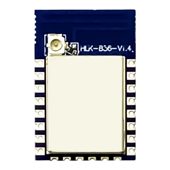
1.5. Product packaging Figure 1 HLK-B36 package size 1.6. Block diagram 3.3V 26MHz UART HLK-B36 1 IPEX Connector GPIO FLASH(2MB) HLK-B36 Module architecture diagram Figure 2. 第 5 页 共 34 页... -
Page 10: Testboard Description
1.7. Testboard description Figure 3 Test board description diagram 1.8. Power requirements Power requirements Power input voltage DC:3.3±0.3V No-load running current 130±50mA Supply current requirements ≥800mA 1.9. WIFI transmission power consumption WIFI transmission power consumption Transmission power Mode Speed Current(ma) consumption 11Mbps 17.5dbm... -
Page 11: Wifi Receive Power Consumption
1.10. WIFI receiving power consumption Mode Speed Current(ma) 11Mbps 54Mbps MCS7 100.5 1.11. Power consumption in each working mode of WIFI Average current State Description Maximum current(3v3) Unit (3v3) wifi Turn off the radio, the 45.2 46.3 initialization MCU is at full speed Keep wifi Keep connected to the... -
Page 12: Receiving Sensitivity In Each Mode Of Wifi
RF average output power,802.11n OFDM Mode MCS7 2. Function description HLK-B36 supports serial port to WIFI STA, serial port to WIFI AP and serial port to BLE mode. 2.1. wifi indicator flashing description Through the blinking mode of the LED indicator, we can quickly know the running status of the module. -
Page 13: One-Key Distribution Mode
4). The wifi indicator flashes quickly: it means that the module is in a STA mode and connected to the wifi hotspot. When there is data transmission, the module LED will flash quickly 2.2. One-key configuration mode For the IOT wifi module, based on cost and performance considerations, there is no touch screen interactive interface like a mobile phone. -
Page 14: Serial Port To Wifi Sta
When the module is in one-key network configuration status, the module needs to be set to one-key network configuration mode. You can use the serial port configuration tool to set the module to one-key network configuration mode. Figure 5 setting as one key configuration 2.3. -
Page 15: Serial Port To Wifi Ap
2.5. Serial port working status conversion After the HLK-B36 is powered on, the default is the transparent transmission mode. By pulling down the pin ES0 (PIN5) for more than 50ms and less than 2s to enter the at command mode, the module will treat the received data as an at command and send the at comand to makes the module enter the transparent transmission mode. -
Page 16: Serial-To-Network Data Conversion
2.6. Serial-to-network data conversion 2.6.1. Module as TCP Server TCP Client TCP Client TCP Server TCP Client TCP Server Figure 9 In this mode, the module monitors the specified port and waits for the TCP Client to connect. After connection, all TCP data is sent directly to the serial port, and the data from the serial port is sent to all TCP Clients. -
Page 17: Module As Udp Server
the TCP Server. Abnormal network disconnection will cause the module to reconnect actively. 2.6.3. Module as UDP Server UDP Client UDP Server UDP Server Figure 11 In this mode, the module opens the local designated port. Once the data sent to this port is received, the module will send the data to the serial port and record the remote ip and port. -
Page 18: Application Field
All commands start with "at" and end with "\r". If the command is not encapsulated in this format, it will not be processed, and the module will return different return values according to different commands. For example: "at+ver=?" The module will return: HLK-B36 (b.1.00.120191206180224) Query command format: at+[command]=? 3.1. Query the current module version:at+ver Grammar rules:... -
Page 19: Local Port Operation:at+Clport
3.2. Local port operation:at+CLport Command Grammar Return and description type at+CLport=8080 Note: When the module is set to tcpclient, the local port of at+CLport=8080 the module is set to port 8080. When the module is set to tcpserver, it is invalid. Range: (1-65535) instruction at+CLport=? at+CLport=? -
Page 20: Set Wifi Connection Mode:at+Netmode
at+dhcpc=? Query at+dhcpc=? instruction Note:1:dhcp mode,0:static ip 3.5. Set wifi connection mode:at+netmode Command Grammar Return and description type at+netmode=3 at+netmode=3 Note:Set the module to ap mode instruction at+netmode=? Query at+netmode=? instruction Note:1:smartconfig 2:sta mode,3:2.4G ap mode 3.6. Set TCP connection mode:at+mode Command Grammar Return and description... -
Page 21: Set The Remote Port When The Module Is Used As A Client:at+Remoteport
at+remoteip=? Query at+remoteip=? 192.168.11.102 instruction Note:Query remote ip 3.8. Set the remote port when the module is used as client :at+remoteport Command Grammar Return and description type at+remoteport=1234 Note:1. When the module is set to tcpserver, this port is the listening port of the module at+remoteport=1234 instruction... -
Page 22: Set The Ssid And Password Of The Module:at+Wifi_Conf
at+reconn=1 Note:System restart 3.11. Set the ssid and password of the module:at+wifi_conf Command Grammar Return and description type at+wifi_conf=HLK-B36_1234,none,12345678 at+wifi_conf=HI-LINK_5FE8 Note:Set the ssid and password of the module, instruction ,none,12345678 none:No definition, format required at+wifi_conf=? Query at+wifi_conf=? HLK-B36_1234,none,12345678 instruction Query Note:... -
Page 23: Query Sta Mode Network Connection Status:at+Wifi_Constate
Note:Query the IP of module,gateway,dns 3.14. Query STA mode network connection status:at+wifi_ConState Command Grammar Return and description type at+wifi_ConState=? Query Disconnected at+wifi_ConState=? instruction Note:In sta mode, the module wifi is not connected, Connected means the network is connected. 3.15. Query module MAC address :at+Get_MAC Command Grammar Return and description... -
Page 24: Set Framing Time:at+Uartpacktimeout
3.17. Set framing time:at+uartpacktimeout Command Grammar Return and description type uartpacktimeout =200 Note:Set the framing time of module to 200ms: range: uartpacktimeout =200 5-5000 instruction If it exceeds the range during setting, it will automatically change to the maximum or minimum value uartpacktimeout Query uartpacktimeout... - Page 25 //Query serial port framing time at+ver=?\r\n\ //Query the firmware version number "; Com_send(query); //Send these data out from the serial port feedback: at+netmode=? 0 at+wifi_conf=? Hi-Link,none,12345678 at+dhcpd=? 0 at+dhcpc=? 1 at+net_ip=? 192.168.15.254,255.255.254.0,192.168.11.1 at+remoteip=? 192.168.11.245 at+remoteport=? 8080 at+remotepro=? tcp at+mode=? server...
-
Page 26: Serial Port To Wifi Client(Static Ip Address)
4.2. Serial port to wifi client(static ip address) code: char *commands_wifi_client_static="\\ at+netmode=2\r\n\ //Set to wireless network card sta mode at+wifi_conf=HI-LINK,none,12345678\r\n\ //Set wifi, encryption method and password at+dhcpc=0\r\n\ //Use static ip at+net_ip=192.168.11.254,255.255.255.0,192.168.11.1\r\n\ //Set the ip of module at+remoteip=192.168.11.245\r\n\ //Set the IP address for remote connection... -
Page 27: Serial Port To Wifi Server(Dynamic Ip Address)
//Socket connects as server at+uart=115200,8,n,1\r\n\ //Set serial port parameters at+uartpacklen=64\r\n\ //Set the framing length at+uartpacktimeout=10\r\n\ //Set framing time at+net_commit=1\r\n\ //Submit parameters at+reconn=1\r\n\"; //Restart module Com_send(commands_wifi_ap); feedback: at+netmode=2 ok at+wifi_conf=HI-LINK,none,12345678 ok at+dhcpc=1 at+remoteip=192.168.11.245 ok 第 23 页 共 34 页... -
Page 28: Reset
at+remoteport=8080 ok at+remotepro=tcp at+mode=server at+uart=115200,8,n,1 ok at+uartpacklen=64 ok at+uartpacktimeout=10 ok at+net_commit=1 4.4. Reset Code: char *commands_device_default="\\ at+default=1\r\n\ //reset Com_send(commands_device_default); feedback: at+default=1 later,Then the module will restart and restore the factory default configuration parameters For more functions,please use the configuration uart and software to set up. The serial port on the left side of the software automatically generates the corresponding setting instructions. -
Page 29: Configuration Software Instructions
4.5. Configuration software instruction Pic 13 Serial port configuration interface 1:Pending command window 2:Serial number selection 3:Working mode selection 4:Wifi name and password 5:Network protocol selection 6:Serial port parameters 7:Submit configuration 8:Query configuration 9:Enter transparent transmission mode 10:Reset 11:Serial return command 12:Set Bluetooth name 13:Set ip 第... -
Page 30: Restore Factory Settings Method
5. Restore factory settings method Press and hold the ES0 button on the bottom panel for more than 6 seconds to restore the factory settings. 6. Bluetooth data transparent transmission Bluetooth data transparent transmission means that after the Bluetooth connection successfully, the module will send the data received from the Bluetooth from the serial port, and the data received by the module's serial port will be sent from the Bluetooth. -
Page 31: Bluetooth Distribution Network
Pic 15 Bluetooth transmission test 7. Bluetooth distribution network The Bluetooth configuration network is to connect to Bluetooth, send the wifi name and password to module, and then the module connects to router according to the received wifi name and password. -
Page 32: Electrical Characteristics
Bluetooth distribution network interface Pic 16 First enter the wifi name and password, and then click the "Start Configuration" button, the phone will send the hotspot name and password to module via Bluetooth, and the module will save it after receiving it, and then restart it, and proceed according to hotspot name and password sent by the phone wifi connection 8. -
Page 33: Current Waveform
Supply current requirement ≥800mA 8.2. Current waveform Module test environment: single module without backplane test, single 2.4G, 3DB antenna. 8.2.1. AP mode Use 3.3V power supply, configure the module to test current in AP mode, average value:110mA,maximum value: 313mA. The detailed current waveform is shown below. apMode transmission current test Pic 17 8.2.2. -
Page 34: Sta Mode
BLE+WiFi transparent transmission current test Pic 18. 8.2.3. STA mode Use 3.3V power supply, configure the module in STA mode to connect to a 2.4g router, the current obtained from the WiFi transparent transmission test, the average value: 110mA, the maximum value: 231mA. -
Page 35: Appendix A Document Revision History
Pic 20. Default mode current test 9.Appendix A Document revision history Version Revision scope Date V1.00 First edition 2020-12-8 FCC Statements (OEM) Integrator has to assure compliance of the entire end-product incl. the integrated RF Module. For 15 B (§15.107 and if applicable §15.109) compliance, the host manufacturer is required to show compliance with 15 while the module is installed and operating. - Page 36 new host device per definition in §15.101. Integrator is reminded to assure that these installation instructions will not be made available to the end-user of the final host device. The final host device, into which this RF Module is integrated" has to be labeled with an auxiliary label stating the FCC ID of the RF Module, such as "Contains FCC ID: 2AD56HLK-B36 "This device complies with part 15 of the FCC rules.
- Page 37 with Part 15 requirements with any type of input signal. 3) The module contains power supply regulation on the module. 4) The module contains a permanently attached antenna. 5) The module demonstrates compliance in a stand-alone configuration. 6) The module is labeled with its permanently affixed FCC ID label. 7) The module complies with all specific rules applicable to the transmitter, including all the conditions provided in the integration instructions by the grantee.
- Page 38 Integration instructions for host product manufacturers according to KDB 996369 D03 OEM Manual v01 2.2 List of applicable FCC rules FCC Part 15.247 2.3 Specific operational use conditions This transmitter/module and its antenna(s) must not be co-located or operating in conjunction with any transmitter.
Need help?
Do you have a question about the HLK-B36 and is the answer not in the manual?
Questions and answers