Advertisement
Quick Links
Automatic Voltage Regulator Models
V-Armor600E/1000E/1500E/2000E
User's Manual
IMPORTANT SAFETY INSTRUCTIONS
(SAVE THESE INSTRUCTIONS)
This manual contains important safety instructions. Please read and follow all instructions carefully
during installation and operation of the unit. Read this manual thoroughly before attempting to unpack,
install, or operate your V-Armor.
CAUTION! To prevent the risk of fire or electric shock, install in a temperature and humidity controlled
indoor area free of conductive contaminants. (See the specifications for the acceptable temperature and
humidity range.)
CAUTION! To reduce the risk of overheating the V-Armor, do not cover the V-Armor's cooling vents and
avoid exposing the unit to direct sunlight or installing the unit near heat emitting appliances such as
space heaters or furnaces.
CAUTION! Do not plug the V-Armor input into its own output.
CAUTION! Do not allow liquids or any foreign object to enter the V-Armor. Do not place beverages or
any other liquid-containing vessels on or near the unit.
CAUTION! In the event of an emergency, press the OFF button and disconnect the power cord from the
AC power supply to properly disable the V-Armor.
CAUTION! Unplug the V-Armor prior to cleaning and do not use liquid or spray detergent.
INSTALLING YOUR V-Armor SYSTEM
UNPACKING
The box should contain the following:
(1)V-Armor Unit1; (2) Power Cord1; (3) User Manual1;
Applications
The V-Armor automatically corrects brownouts (by boosting low voltage) and over voltages (by stepping
down high voltage) from the power utility service to levels that are safe for computers, as well as other
sensitive equipment. The V-Armor provides the highest degree of protection from line voltage sags and
swells.
The total power consumption of all equipment plugged into the V-Armor must not exceed the "Maximum
Output Power Capacity" rating listed in the Specifications table.
BASIC OPERATION
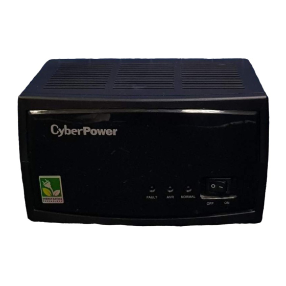
FRONT PANEL DESCRIPTION
1. Power Switch
Press the power switch to turn the ON / OFF V-Armor.
2. Normal Mode LED
The green LED will light when utility power is normal.
3. AVR Mode LED
The yellow LED will light when utility power is abnormal and the unit will work in AVR mode.
The yellow LED will flash every 3 seconds when input line voltage is not in acceptable range and the unit
will switch off the outputs.
4. Fault LED
The red LED will light when fault or over load occurs.
REAR PANEL DESCRIPTION
K01-C000035-00
1.
AC Inlet
Connect to utility power through the input power cord.
2.
Input Circuit Breaker
The circuit breaker provides optimal overload protection.
3.
AC outlet
The V-Armor provides outlets for connected equipment to insure temporary uninterrupted
operation during a power failure and against surges and spikes.
4.
Fan
The V-Armor provides fan for heat dissipation (for V-Armor1000E/1500E/2000E).
Model
Capacity (VA)
Capacity (Watts)
Nominal Voltage
Input
Input Voltage Range
Frequency
Output
Output Voltage
Regulation
Overload Protection
Surge Protection
Audible Alarms
Overload/Fault
Environmental
Operating Temperature
Operating Relative
Humidity
Physical
Maximum Dimensions
(HxWxD) (mm)
TECHNICAL SPECIFICATIONS
V-Armor600E
V-Armor1000E
V-Armor1500E
600
1000
600
1000
220/230Vac
165Vac-278Vac
50 / 60Hz
220/230Vac +/-10%
Firmware & Circuit Breaker
445 Joules (L-N)
Continuously sounding
0° C to 40° C
0 to 90%
150 x 120 x 200 mm
V-Armor2000E
1500
2000
1500
2000
Advertisement

Related Manuals for CyberPower V-Armor600E


Summary of Contents for CyberPower V-Armor600E
- Page 1 REAR PANEL DESCRIPTION Automatic Voltage Regulator Models V-Armor600E/1000E/1500E/2000E User’s Manual K01-C000035-00 IMPORTANT SAFETY INSTRUCTIONS AC Inlet (SAVE THESE INSTRUCTIONS) Connect to utility power through the input power cord. This manual contains important safety instructions. Please read and follow all instructions carefully during installation and operation of the unit.
- Page 2 V-Armor industry. Reduce Energy Cost with GreenPower Technology CyberPower’s goal is not only to provide eco-friendly products but also to bring the best value for consumers. The advanced energy-saving design improves the operating efficiency and eliminates waste energy consumption. As a result, consumers will enjoy significant energy cost savings with the adoption of GreenPower technology.
Need help?
Do you have a question about the V-Armor600E and is the answer not in the manual?
Questions and answers