Table of Contents
Advertisement
Quick Links
Advertisement
Table of Contents

Related Manuals for R.V.R. Elettronica HC3 LCD


Summary of Contents for R.V.R. Elettronica HC3 LCD
- Page 1 HC3 LCD User Manual Volume 1 Manufactured by Italy...
- Page 2 Version Date Reason Editor 11/02/2002 New version D. Canazza HC3 - User Manual Version 1.0 © Copyright 2002 R.V.R. Elettronica SpA Via del Fonditore 2/2c - 40138 - Bologna (Italia) Telefono: +39 051 6010506 Fax: +39 051 6011104 Email: info@rvr.it Web: www.rvr.it...
-
Page 3: Table Of Contents
Table of Content 1. Preliminary instructions 2. Warranty 3. First Aid 3.1 Treatment of electrical shocks 3.2 Treatment of electrical Burns 4. General Description 5. Installation and Use 5.1 Preparation 5.2 Operation 5.3 Software 5.3.1 RF Power switch menu (Fnc) 5.3.2 Power menu (Pwr) 5.3.3 Power Amplifier menu (P.A.) 5.3.4 Threshold setting menu... - Page 4 This page was intentionally left blank Rev. 1.0L - 16/05/01 User Manual...
-
Page 5: Preliminary Instructions
In this case can be requested to user to take the necessary measures. R.V.R. Elettronica SpA reserves the right to modify the design and/or the technical specifications of the product and this manual without notice. User Manual Rev. - Page 6 Pagina lasciata intenzionalmente in bianco This page was intentionally left blank 2 / 28 Rev. 1.0L - 16/05/01 User Manual...
-
Page 7: Warranty
2. Warranty Any product of R.V.R. Elettronica is covered by a 12 (twelve) month warranty. For components like tubes for power amplifiers, the original manufacturer’s warranty applies. R.V.R. extends to the original end-user purchaser all original manufacturers warranties which are transferable and all claims are to be made directly to R.V.R. - Page 8 Replacement and warranty parts may be order from the following address. Be sure to include the equipment model and serial number as well as part description and part number. R.V.R. Elettronica SpA Via del Fonditore, 2/2c 40138 BOLOGNA ITALY Tel.
-
Page 9: First Aid
3. First Aid The personnel employed in the installation, use and maintenance of the device, shall be familiar with theory and practice of first aid. 3.1 Treatment of electrical shocks 3.1.1 If victim is not responsive follow the A-B-C's of basic life support •... -
Page 10: Treatment Of Electrical Burns
3.1.2 If victim is responsive • Keep them warm • Keep them as quiet as possible • Loosen their clothing (a reclining position is recommended) • Call for medical help as soon as possible 3.2 Treatment of electrical Burns 3.2.1 Extensive burned and broken skin •... -
Page 11: General Description
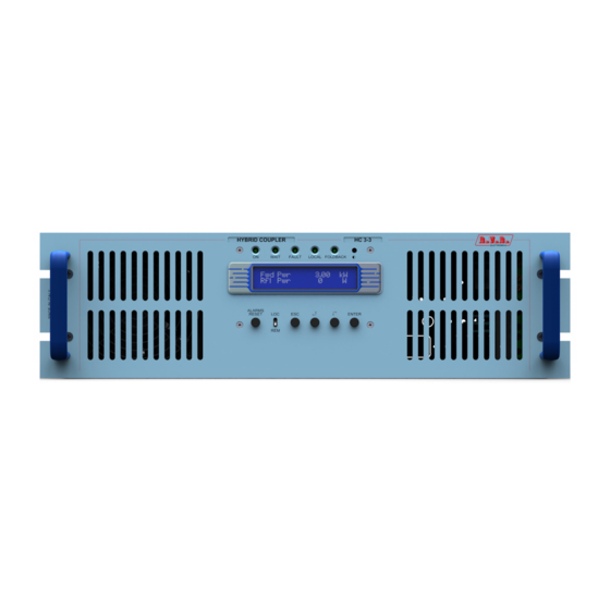
4. General Desciption The HC3, produced by R.V.R. Elettronica, is a hybrid coupler at 3 way realized in "Strip-Lines" technology. Its function is to split into three portions the RF signal coming from a RF exciter, adjusting the relative phases, to pass them through three external RF power amplifiers and then to combine the output of the amplifiers into a single RF amplified signal to be forwarded to the antenna output. - Page 12 The management software of the HC3 is based on a menu system. The user can navigate through the menu system using four buttons, ESC, move LEFT/UP, move RIGHT/DOWN and ENTER. A fifth button is used to reset the alarm counters, if any alarm has been triggered before. Five LEDs on the front panel of the amplifier show the current status of the machine: ON/OFF, WAIT, FAULT, LOCAL and FOLDBACK A switch on the front panel allows to select the LOCAL or REMOTE working mode:...
-
Page 13: Installation And Use
5. Installation and use This chapter is intended to summarize the necessary points for the installation of the device. In case any of the arguments is unclear, for example when you use the combiner for the first time, we suggest to carefully read the whole manual. 5.1 Preparation Unpack the HC3 and before any other operation check the unit for any shipping damage;... -
Page 14: Software
The management of the HC3 is performed by a generic software used in different classes of equipment produced by R.V.R. Elettronica SpA, like the HC combiners or the RF amplifiers PJ500M-C and PJ1000M. - Page 15 Switch on ~ 5 sec Main screen Menu Selection ENTER Switch Menu ENTER Power Menu ENTER Power Amp. Menu ENTER Threshold Setting ENTER Alarms Menu ENTER Miscellaneous Menu ENTER Version Menu After a few seconds, the main screen will be displayed, reporting the values od Forward power and Reflected power: The management software will remain indefinitely in this default screen, until the user pushes the ESC button.
-
Page 16: Rf Power Switch Menu (Fnc)
5.3.1 RF Power switch menu (Fnc) From this menu, the user can “switch” ON and OFF the hybrid coupler. The result of this command is that when the HC3 is put in OFF mode, the inner conductor of the “Alarm” connector is shorted to ground, so that the exciter is put in stand-by mode (this will happen only if provided with an interlock connector, and if correctly connected with the hybrid coupler). -
Page 17: Power Amplifier Menu (P.a.)
5.3.3 Power Amplifier menu (P.A.) This multi-line scrollable menu reports to the user some internal measurement of the device: • Voltage (VPA) - Not active • Current (IPA) - Not active • Efficiency - Not active • Temperature • Mains voltage (Mains - percentage variation with respect to the nominal voltage) The complete aspect of the screen is the following figure (please note that only two lines at a time are visible, use the UP and DOWN buttons to scroll): 5.3.4 Threshold setting menu... -
Page 18: Alarms Menu
The thresholds are expressed as percentage of full-scale value of the relevant quantity. The full scakle values for the HC5 are the following: • Forward Power 3000W • Reflect Power 300W To change the values of the thresholds, execute the following procedure: •... -
Page 19: Various Menu
The function of this menu is essentially a help for the technician to identify the causes of possible malfunctions of the transmitter. 5.3.6 Various menu Two operations can be performed using this menu: • Setup the address of the I C serial bus type connection •... -
Page 20: Version Menu
5.3.7 Version menu This menu shows the hardware (H.V.) and software versions (S.V.) of the machine. 5.3.8 Protection sistem The protection system implemented in hybrid coupler is based on two types of reactions, the “Foldback” and the temporary disabling. 5.3.8.1 Foldback The foldback circuit controls the level of a dc voltage that is available on the dedicated BNC connector (F.BACK) on the rear of the HC3. - Page 21 In general, the reduction of the RF power generated by the exciter will reduce the variable that casued the foldback intervention, so that a new stability point is reached. If any reason makes it impossible to reach a new stable point, the protection system of the HC3 will react with its Shut off/Restart procedure.
- Page 22 Pagina lasciata intenzionalmente in bianco This page was intentionally left blank 18 / 28 Rev. 1.0L - 16/05/01 User Manual...
-
Page 23: Controls, Indicators And Connectors
6. Controls, Indicators and Connectors This chapter describes the front and rear panels of the HC3, with a brief indication of all the different components. 6.1 Front Panel [1] DISPLAY LCD Display. [2] ON Green LED, lit when the hybrid coupler is switched on. [3] WAIT Yellow LED indicating that the amplifier is waiting for a condition that is blocking the power output to be removed. -
Page 24: Rear Panel
6.2 Rear Panel [1] INPUT Exciter’s R.F. Input connector (N-type). [2] OUTPUT 1 Power Splitter Output 1 (N-type connector) to drive Power Amplifier A. [3] OUTPUT 2 Power Splitter Output 2 (N-type connector) to drive Power Amplifier B. [4] OUTPUT 3 Power Splitter Output 3 (N-type connector) to drive Power Amplifier C. -
Page 25: Technical Specifications
7. Technical Specifications 7.1 Dimensional and Environmental Specifications Cabinet Dimensions 447.0 mm x 132.5 mm x 507.5 mm Panel Dimensions 483 mm x 132.5 mm Weight 17.5 Kg -10 °C ÷ 50 °C Operating Temperature Range Umidity 90% Maximum, whithout condensation 7.2 Electrical Specifications A.C. - Page 26 Pagina lasciata intenzionalmente in bianco This page was intentionally left blank 22 / 28 Rev. 1.0L - 16/05/01 User Manual...
- Page 27 8. Modules Identification 8.1 Upper view Power Splitter Board Transformer Power Coupler Board User Manual Rev. 1.0L - 16/05/01 23 / 28...
- Page 28 8.2 Bottom view Unbal Power Card Voltage Changer Blowers Temperature Sensor Remote Card 24 / 28 Rev. 1.0L - 16/05/01 User Manual...
-
Page 29: Electrical Description
9. Electrical Description HC3 is composed of different modules wired between them with connectors, allowing for easy servicing or module substitution. RF output to Amp 1 RF input from exciter RF output RF Splitter to Amp 3 Telemetry, RS232, Display, Keys Interlock ... -
Page 30: System Compensation
8.2 System Compensation 1) On the coupler instrument, select the forward power measurement mode. 2) Remove the coupler’s upper cover. 3) Set the desired system working frequency on the exciter. 4) Set the output power of the exciter so that the system output forward power is at 80% of the nominal value. -
Page 31: Power Combiner
Adjust the variable capacitors (3) and (4), relative to the second amplifier output, to maximize the power level measured by the coupler’s instrument. Adjust the variable capacitors (5) and (6), relative to the third amplifier output, to maximize the power level measured by the coupler’s instrument. Repeat steps 6, 7 and 8 until the system power reaches its maximum. - Page 32 This page was intentionally left blank 28 / 28 Rev. 1.0L - 16/05/01 User Manual...
- Page 33 11. Calibration Procedures 11.1 Introduction This chapter describes the calibration procedures that are necessary to do when you have replaced some cards or some devices, or in case of a complete replacement of the equipment into of a transmitter station. All calibrations must be executed switching on all equipment at the minimum power.
- Page 34 FOLBACK intervention adjustment • Be sure that the exciter is not operative. • Measure the voltage on the PIN1 of JP7 on the power supply card with a multimeter, than rotate the trimmer TR9 to obtain a voltage of 0V. Forward power reading adjustment •...
Need help?
Do you have a question about the HC3 LCD and is the answer not in the manual?
Questions and answers