Advertisement
Advertisement
Table of Contents

Related Manuals for SeeTech iH-110 Series


Summary of Contents for SeeTech iH-110 Series
- Page 1 Cash counter & Discriminator Rev. 1.0.2 Date: 2017. 02. 08...
- Page 2 Series Service Manual Records of Revision Rev. YYYY-MM-DD Chief Contents In Charge Issued 2016-09-11 First Edition. Kelly 2016-12-06 Main Screens of the machine are changed. Kelly 2016-12-19 UV Calibration is changed. Kelly 2017-02-08 CIS Calibration is changed. Kelly Hitachi Terminal Solutions Korea Co., Ltd.
-
Page 3: Table Of Contents
Series Service Manual - Contents – 1. Appearance ........................4 2. Disassemble & Assemble .................... 5 3. Upgrade ........................40 4. Calibration ........................42 5. Data Acquisition......................53 6. Machine Setting Menu(Preparing) ................56 7. Engineer Setting Menu(Preparing) ................57 8. -
Page 4: Appearance
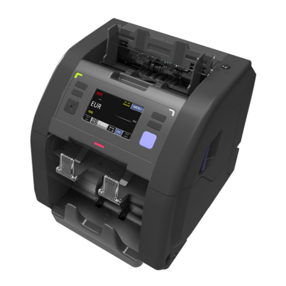
Series Service Manual 1. Appearance <Front View> LCD Display Hopper Hopper Guide Operation Keys Reject Pocket Stacker <Rear View> Gap Adjust Knob Power Supply Socket USB-H Power Switch (PC) External USB-S Printer Display (Devices) Hitachi Terminal Solutions Korea Co., Ltd. -
Page 5: Disassemble & Assemble
Series Service Manual 2. Disassemble & Assemble 2-1. UPPER SIDE COVER and LOWER SIDE COVER Right Side Left Side Upper Side Lower Side Hitachi Terminal Solutions Korea Co., Ltd. - Page 6 Series Service Manual 1) Left and Right Side Lower Cover are assembled with 3 pcs of TERAS BOLT. 2) Remove 3 pcs of TERAS BOLT as below. 3) By pulling the cover as below picture, separate Right Lower Side Cover from the machine.
- Page 7 Series Service Manual 4) Remove Left Lower Side Cover as the same method. 5) Left and Right Side Upper Cover are assembled with 3 pcs of SEM'S BOLT. Hitachi Terminal Solutions Korea Co., Ltd.
- Page 8 Series Service Manual 6) Remove 3 pcs of SEM'S BOLT as below. 7) Separate Right Upper Side Cover from the machine. Hitachi Terminal Solutions Korea Co., Ltd.
- Page 9 Series Service Manual 8) Remove Left Upper Side Cover as the same method. 9) When you want to assemble Left&Right Side Upper and Lower Cover, reassemble in reverse order of disassembly. *Check Points and Tips* - When assemble Left&Right Side Upper Cover, you need adjust Screw hole correctly as below.
- Page 10 Series Service Manual - When assemble Left&Right Side Lower Cover, put the front area of the covers first as below. - You can remove Left&Right Side Upper Cover without disassemble Left&Right Side Lower Cover. Hitachi Terminal Solutions Korea Co., Ltd.
- Page 11 Series Service Manual 2-2. LOWER REAR COVER and MODULE REAR COVER 1) Remove UPPER SIDE COVER and LOWER SIDE COVER first. 2) Go to back side. 3) LOWER REAR COVER is assembled with 6 pcs of TERAS BOLT. 4) Remove 6 pcs of TERAS BOLT as below.
- Page 12 Series Service Manual 5) MODULE REAR COVER is assembled with 4 pcs of SEM'S BOLT. 6) Remove 4 pcs of SEM'S BOLT as below. 7) When you want to assemble LOWER REAR COVER and MODULE REAR COVER, reassemble in reverse order of disassembly.
- Page 13 Series Service Manual 2-3. Front Cover & Hopper Cover 1) Remove UPPER SIDE COVER. 2) Go to the left side and remove 2 screws as below. 3) Go to the right side and remove 2 screws as below. Hitachi Terminal Solutions Korea Co., Ltd.
- Page 14 Series Service Manual 4) Hold HOPPER COVER and lift ROTARY BOLT UNIT slightly. 5) Remove HOPPR COVER. 6) Hold FRONT COVER as below and lean back it slightly.3 kinds of harnesses are connected to FRONT BOARD. Hitachi Terminal Solutions Korea Co., Ltd.
- Page 15 Series Service Manual 7) Separate 3 harnesses and remove FRONT COVER from the machine. Hitachi Terminal Solutions Korea Co., Ltd.
- Page 16 Series Service Manual 8) When you want to assemble FRONT COVER, reassemble in reverse order of disassembly. *Check Points and Tips* - When assemble HOPPER COVER, adhere it to Machine as below, tighten screws. Hitachi Terminal Solutions Korea Co., Ltd.
- Page 17 Series Service Manual 2-4. MODULE 1 1) Remove UPPER SIDE COVER and LOWER SIDE COVER. 2) Remove LOWER REAR COVER and MODULE REAR COVER. 3) Go to left side of the machine. 4) Remove IH-BELT S3M318. Hitachi Terminal Solutions Korea Co., Ltd.
- Page 18 Series Service Manual 5) Remove ST-BELT (S3M 195-6). 6) Remove ST-BELT (S2M 142-6). Hitachi Terminal Solutions Korea Co., Ltd.
- Page 19 Series Service Manual 7) Remove 2 screws as below. 8) Go to right side of the machine. Hitachi Terminal Solutions Korea Co., Ltd.
- Page 20 Series Service Manual 9) Remove 2 screws as below. Hitachi Terminal Solutions Korea Co., Ltd.
- Page 21 Series Service Manual 10) Unlock 3 HARNESS MOUNT and separate 8 kinds of Harness from MAIN BOARD. Hitachi Terminal Solutions Korea Co., Ltd.
- Page 22 Series Service Manual 11) Go to back side. 12) Hold MODULE with both hands as below and pull and separate it from Machine. Hitachi Terminal Solutions Korea Co., Ltd.
- Page 23 Series Service Manual 13) When you want to assemble MODULE, reassemble in reverse order of disassembly. *Check Points and Tips* - When assemble MODULE, you need to check assemble points as below. Point1: Adjust Gear(15- 2625T) to groove on UPPER SIDE RIGHT PLATE.
- Page 24 Series Service Manual - Assembly order of 3 belts is as below. ST-BELT (S2M 142-6) -> IH-BELT S3M318 -> ST-BELT (S3M 195-6) Hitachi Terminal Solutions Korea Co., Ltd.
- Page 25 Series Service Manual 2-5. MODULE 2 Hitachi Terminal Solutions Korea Co., Ltd.
- Page 26 Series Service Manual 1) Go to UP SENSOR MODULE. 2) Remove 6 screws and remove UPPER COVER PLATE as below. Hitachi Terminal Solutions Korea Co., Ltd.
- Page 27 Series Service Manual 3) Remove 4 screws and disassemble MG SENSOR from MODULE. Hitachi Terminal Solutions Korea Co., Ltd.
- Page 28 Series Service Manual 4) Remove 2 screws and separate UV TOP SENSOR. Hitachi Terminal Solutions Korea Co., Ltd.
- Page 29 Series Service Manual 5) Remove 4 screws and separate US TOP LEFT SENSOR and US TOP RIGHT SENSOR. Hitachi Terminal Solutions Korea Co., Ltd.
- Page 30 Series Service Manual 6) Open MODULE. 7) Remove 2 screws from CIS SENSOR TOP. Hitachi Terminal Solutions Korea Co., Ltd.
- Page 31 Series Service Manual 8) Lift CIS SENSOR TOP slightly. 9) Unlock CIS SENSOR TOP Connector. 10) Separate CIS SENSOR TOP from MODULE. Hitachi Terminal Solutions Korea Co., Ltd.
- Page 32 Series Service Manual 11) Go to DOWN SENSOR MODULE. 12) Remove 2 screws and separate UV BOT SENSOR. Hitachi Terminal Solutions Korea Co., Ltd.
- Page 33 Series Service Manual 13) Remove 4 screws and separate US BOT LEFT SENSOR and US BOT RIGHT SENSOR. Hitachi Terminal Solutions Korea Co., Ltd.
- Page 34 Series Service Manual 14) Open MODULE. Hitachi Terminal Solutions Korea Co., Ltd.
- Page 35 Series Service Manual 15) Remove 2 screws from CIS SENSOR BOTTOM. 16) Lift CIS SENSOR BOTTOM slightly. 17) Unlock CIS SENSOR BOTTOM Connector. Hitachi Terminal Solutions Korea Co., Ltd.
- Page 36 Series Service Manual 18) Separate CIS SENSOR BOTTOM from MODULE. Hitachi Terminal Solutions Korea Co., Ltd.
- Page 37 Series Service Manual 2-6. MAIN BOARD 1) Remove UPPER RIGHT SIDE COVER and LOWER RIGHT SIDE COVER. 2) Remove LOWER REAR COVER. 3) MAIN BOARD is placed on Right Side of the machine. 4) Separate all connectors from MAIN BOARD.
- Page 38 Series Service Manual 5) Remove 7 screws and separate MAIN BOARD from Machine. 6) 5 harnesses are connected to rear side of MAIN BOARD. Separate the harnesses from MAIN BOARD. Hitachi Terminal Solutions Korea Co., Ltd.
- Page 39 Series Service Manual 7) Remove MAIN BOARD from the machine. Hitachi Terminal Solutions Korea Co., Ltd.
-
Page 40: Upgrade
Series Service Manual 3. Upgrade 1. Remove all files from USB Stick. 2. Copy “Upgrade” folder to USB Stick. 3. “Upgrade” folder must be placed in the root of USB Stick as below. (The same way with ST-350) 4. Connect USB Stick to iH-110. - Page 41 Series Service Manual 6. Enter MENU-> Comm. Info. -> select USB . 8. Touch Upgrade and upgrade is started. 7. When “Upgrade Success!!” is shown, reboot the machine. Hitachi Terminal Solutions Korea Co., Ltd.
-
Page 42: Calibration
Series Service Manual 4. Calibration *Calibration Papers* ※ In case of CIS Setting Paper 2, 10 pcs are provide by default. CIS Setting Paper 2 must be clean. Before calibration, please check this. 1. Turn on the machine. 2. Enter MENU -> MENU-> Comm. Info. -> select PIN. - Page 43 Series Service Manual 3. Enter Pincode. (0000) 4. Press START Key and go to the previous menu tree. 5. Hidden menus are shown as below. 6.Click “Machine Setting”. Hitachi Terminal Solutions Korea Co., Ltd.
- Page 44 Series Service Manual 4-1. CNT Calibration ① Press “↓” Button and enter CNT Calibration mode. ② Click SETUP icon and start CNT calibration. ③ After calibration is completed, try to check State of each sensors. Hitachi Terminal Solutions Korea Co., Ltd.
- Page 45 Series Service Manual 4-2. CIS Calibration ① Press “LS1” Key (or click “SETUP” icon) and enter CIS Calibration Mode. ② “Caution” message is shown. ③ Open Rear Cover and put CIS Calibration Paper 1 on CIS Sensor as below.
- Page 46 Series Service Manual ④ Press “LS1” Key (or click “SETUP” icon) and start Calibration. ⑤ When Calibration is completed, “Caution” message is shown again. Remove CIS Calibration Paper and close Rear Cover. ⑥ Press Press “LS1” Key (or click “IRT” icon) ⑦...
- Page 47 Series Service Manual ⑧ Press “LS2” Key or click “CALIB” icon. ⑨ Put a pcs of CIS Setting Paper 2 on Hopper. The paper is counted automatically. If “Try again” message is shown, count the same paper again. Hitachi Terminal Solutions Korea Co., Ltd.
- Page 48 Series Service Manual ⑩ When Calibration for CIS Setting Paper 2 is finished successfully, “Complete!!!!” is shown as below. ⑪ Press “START” Key and go to the first screen. ⑫ Press “RS2”key or click “VIEW” icon. ⑬ The screen is changed as below.
- Page 49 Series Service Manual ⑭ Put a TEST note(banknote) on Hopper and the note is counted automatically. ⑮ Press “RS2”Key and the scanned image is shown. 4 kinds of images are scanned and you can check it by press “←” or “→” Key.
- Page 50 Series Service Manual 4-3. UV Calibration ① Go to UV Calibration mode. Screen is changed as below and you can a message about Paper as below. There are two kinds of UV Setting Paper as below. If you have OLD UV setting paper, select [Paper] OLD first and go to next step.
- Page 51 Series Service Manual ③ When OFFSET SETUP is “DONE”, put 10 pcs of UV Setting Papers on Hopper with the correct direction. ④ Setting Papers are counted automatically. If UV Setting is completed, “”UV SETUP COMPLETE” message is shown.
- Page 52 Series Service Manual 4-4. TOUCH Calibration ① Go to TOUCH Calibration mode. ② Press “LS1” Key and TOUCH Calibration mode. ③ Touch 5 points randomly and calibration is completed. Hitachi Terminal Solutions Korea Co., Ltd.
-
Page 53: Data Acquisition
Series Service Manual 5. Data Acquisition 1. Prepare USB Stick for saving the data. 2. Connect USB Stick to iH-110. 3. Turn on the power of the machine. 4. Enter MENU-> Comm. Info. -> select DATA . Hitachi Terminal Solutions Korea Co., Ltd. - Page 54 Series Service Manual 5. Select USB->DATA Acq. 6. Go to Main Screen by pressing Start key. 7. Select Local Currency which you want to save the data. (For example, EUR) 8. When you put a note which you want to save the data, the note is counted and the data is saved to USB Stick automatically.
- Page 55 Series Service Manual 9. A new folder is created to USB Stick and all data is saved to the folder. Hitachi Terminal Solutions Korea Co., Ltd.
-
Page 56: Machine Setting Menu(Preparing)
Series Service Manual 6. Machine Setting Menu - preparing Hitachi Terminal Solutions Korea Co., Ltd. -
Page 57: Engineer Setting Menu(Preparing)
Series Service Manual 7. Engineer Setting Menu - preparing Hitachi Terminal Solutions Korea Co., Ltd. -
Page 58: Specification
Series Service Manual 8. Specification Currency Up to 80 currencies Value Counting Max 1300 notes/min Capture and Records: Operating Speed OCR, MICR, Barcode etc. with Full Color 700 ~ 900 notes/min Image Hopper 500 notes (Max 700 notes) Pocket Capacity... -
Page 59: Error Code
Series Service Manual 9. Error code Error Explanation CHAIN The gap between two notes is narrow. SKEW L The note is skewed to the left. SKEW R The note is skewed to the right. DOUBLE Two notes are inserted together. - Page 60 Series Service Manual Error Explanation SN UNCERTAIN The recognition rate of seiral numbers is bad. Serial number from Black List is recognized. (When SN Black List is SN BLACK LIST BAR WRONG SIDE Not found barcode. BAR SEARCH Not found the start position of barcode pattern.
-
Page 61: Trouble Shooting(Preparing)
Series Service Manual 10. Trouble Shooting - preparing Hitachi Terminal Solutions Korea Co., Ltd. -
Page 62: Block Diagram
Series Service Manual 11. Block diagram Hitachi Terminal Solutions Korea Co., Ltd. - Page 63 Series Service Manual Hitachi Terminal Solutions Korea Co., Ltd.
- Page 64 Series Service Manual Office & Factory 7-6, 4-gil, Samsung 1-ro,Hwaseong-si, Gyeonggi-Do, Korea TEL: 82 31 211 8761 / FAX: 82 31 211 8763 www.e-seetech.com Hitachi Terminal Solutions Korea Co., Ltd.
Need help?
Do you have a question about the iH-110 Series and is the answer not in the manual?
Questions and answers
Currency not going to the stacker