
Related Manuals for SeeTech ST-150


Summary of Contents for SeeTech ST-150
- Page 1 Currency Fitness Sorter, Authenticator with 2 Pocket Rev : 1.6 Date : 04 September, 2012...
- Page 2 SERVICE MANUAL FOR ST-150(F) Record of Revision Rev.no Main Contents In charge Date New release Mr.Cha 4 March,2011 Add to Disassemble & assemble 19 May, 2011 Modify Chapter 5.Calibration 30 May, 2011 Modify Printer port diagram. (Page 56~58) Modify Chapter 5.Calibration 14 August, -Modify 5.2 MG CALIBRATION (Page 41)
-
Page 3: Table Of Contents
SERVICE MANUAL FOR ST-150(F) - Contents – 1. PURPOSE ................................5 2. APPEARANCE ..............................5 2.1. E ................................5 XTERIOR 2.2. S ................................7 ENSOR 3. DISASSEMBLE & ASSEMBLE ..........................9 3.1. M TFT LCD ..........................9 ERLIN BOARD AND –... - Page 4 SERVICE MANUAL FOR ST-150(F) ERROR CODE ..............................47 4/47 SeeTech...
-
Page 5: Purpose
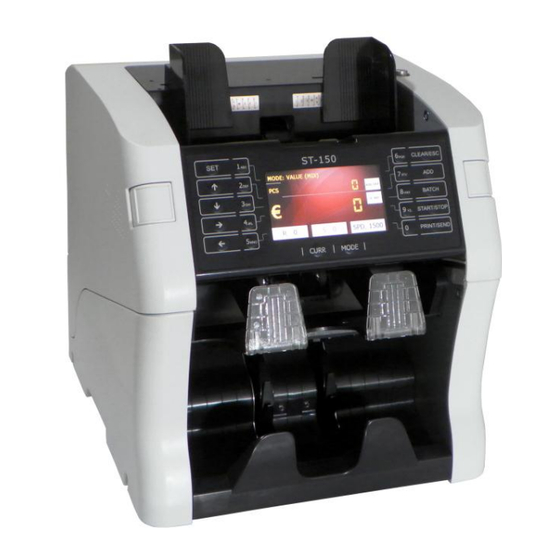
SERVICE MANUAL FOR ST-150(F) 1. PURPOSE This document is for Maintenance and service of Magner175 series. 2. APPEARANCE 2.1. Exterior Hopper Guide Hopper LCD Display Operation Keys Reject Pocket Stacker 5/47 SeeTech... - Page 6 SERVICE MANUAL FOR ST-150(F) Gap Adjust Knob Power Supply Socket Power Switch USB-H USB-S (PC) (Devices) Serial-1 Serial-2 (PC, Printer) (PC, Printer) 6/47 SeeTech...
-
Page 7: Sensor
SERVICE MANUAL FOR ST-150(F) 2.2. Sensor Up Sensor Module Counter LED Sensor IR Sensor UV Rear Sensor MG Sensor Down Sensor Module Counter Sensor CIS Sensor TDS Roller UV Front Sensor 7/47 SeeTech... - Page 8 SERVICE MANUAL FOR ST-150(F) Lower Drive Body Reject Sensor Jam 1 sensor Jam 2 sensor Hopper sensor Stacker sensor 8/47 SeeTech...
-
Page 9: Disassemble & Assemble
SERVICE MANUAL FOR ST-150(F) 3. DISASSEMBLE & ASSEMBLE 3.1. Merlin board and TFT LCD Loosen screw of left side. Loosen screw of rignt side. Loosen screw of upper left side. Press release button both side and open front cover. Loosen screw of upper right side. - Page 10 SERVICE MANUAL FOR ST-150(F) Loosen screw of upper right side. Loosen screw of upper left side. Loosen screw of left side and remove Loosen screw of right side and remove upper side right cover. upper side left cover. Loosen 2 screws of left side.
- Page 11 SERVICE MANUAL FOR ST-150(F) #15-1 #15-2 #15-3 Remove front cover assembly. Disconnect #15-1, #15-2, #15-3 cable on Merlin board. #3-1 #3-2 #3-3 Disconnect #3-1, #3-2, #3-3 cable on Merlin board. #1-1 #1-2 Disconnect #1-1, #1-2, #2 cable on Merlin board.
- Page 12 SERVICE MANUAL FOR ST-150(F) Loosen 4 screws on Merlin board. Remove Merlin board and disconnect TFT LCD cable. Remove 4 screws and disassemble TFT LCD. 12/47 SeeTech...
-
Page 13: Detection Module - Argos Board
SERVICE MANUAL FOR ST-150(F) 3.2. Detection Module – Argos board Loosen 4 screws of rear cover. Loosen 2 screws of middel knob and remove rear cover. Loosen 4 screws of middle cover. Loosen 4 screws of middle cover. #17-1 #6-2... - Page 14 SERVICE MANUAL FOR ST-150(F) Separate Argos board from board Loosen 2 screws on Argos board. mount and then disassemble Argos board 14/47 SeeTech...
-
Page 15: Module - Center Mg Sensor & Side Mg Sensor
SERVICE MANUAL FOR ST-150(F) 3.3. Module – Center MG sensor & Side MG sensor Same procedure 3.2 then follows next as below. Remove the screws in red circles and Disassemble right side MG sensor then disassemble Center MG sensor board. -
Page 16: Module
SERVICE MANUAL FOR ST-150(F) 3.4. Module Loosen screw of left side. Loosen screw of rignt side. Loosen screw of upper left side. Press release button both side and open front cover. Loosen screw of upper right side. Lift up Middle knob to open rear cover. - Page 17 SERVICE MANUAL FOR ST-150(F) Loosen screw of upper right side. Loosen screw of upper left side. Loosen screw of left side and remove Loosen screw of right side and remove upper side right cover. upper side left cover. Remove 2 belts from Pulley.
- Page 18 SERVICE MANUAL FOR ST-150(F) Loosen 7 screws of left side . Loosen 7 screws of right side. Screw size are 3X6 in yellow circles Screw size are 3X6 in yellow circles and 3X8 in blue circles.. and 3X8 in blue circles..
- Page 19 SERVICE MANUAL FOR ST-150(F) When the detection module is removed, be careful #1-1, #1-2, #5-1, #5-2, #12 cables. Take out Module assembly from machine. 19/47 SeeTech...
-
Page 20: Motor Drive Board
SERVICE MANUAL FOR ST-150(F) 3.5. Motor drive board Loosen 3 screws of lower right side Loosen screw and remove lower right cover. side cover. Disconnect all cable from Motor drive Loosen 4 screws and remove Motor board. drive board. 20/47... -
Page 21: Comm Board
SERVICE MANUAL FOR ST-150(F) 3.6. COMM board Loosen 2 screws. Turn the machine on its side to loose screw. Disconnect 3 cables Loosen 2 screws. 21/47 SeeTech... -
Page 22: Main Motor
SERVICE MANUAL FOR ST-150(F) 3.7. Main motor Loosen screw of left side. Loosen screw of rignt side. Loosen screw of upper left side. Press release button both side and open front cover. Loosen screw of upper right side. Lift up Middle knob to open rear cover. - Page 23 SERVICE MANUAL FOR ST-150(F) Loosen screw of upper right side. Loosen screw of upper left side. Loosen screw of left side and remove Loosen screw of right side and remove upper side right cover. upper side left cover. Loosen 2 screws of left side.
- Page 24 SERVICE MANUAL FOR ST-150(F) #15-1 #15-2 #15-3 Remove front cover assembly. Disconnect #15-1, #15-2, #15-3 cable on Merlin board. #3-1 #3-2 #3-3 Disconnect #3-1, #3-2, #3-3 cable on Merlin board. #1-1 #1-2 Disconnect #1-1, #1-2, #2 cable on Merlin board.
- Page 25 SERVICE MANUAL FOR ST-150(F) Disconnect connector from Encoder Loosen 4 screws of left side. sensor. Loosen 4 screws of right side. Disconnect connector in red circle and open Low drive assembly. Remove belt in red circle. Remove Pulley and loosen 3 screws.
-
Page 26: Kicker Motor
SERVICE MANUAL FOR ST-150(F) 3.8. Kicker Motor Same procedure of 3.7 then follows next as below. Remove belt and pulley of right side. Loosen 3 screws. 26/47 SeeTech... -
Page 27: Stacker Motor
SERVICE MANUAL FOR ST-150(F) 3.9. Stacker Motor Loosen 3 screws of lower left side Press release button both side and cover. open front cover. Loosen screw and remove lower left Loosen 3 screws of lower right side side cover. cover. - Page 28 SERVICE MANUAL FOR ST-150(F) Loosen 2 screws of right side. Remove Reject pocket. Loosen screw of left side. Loosen screw of left side. Fix position the shaft by slender driver Disconnect connector and remove as yellow circle and remove the screw stacker pocket.
- Page 29 SERVICE MANUAL FOR ST-150(F) Remove E-rings separate Remove Pin. stacker. Loosen 3 screws and remove stacker motor. 29/47 SeeTech...
-
Page 30: Solenoid
SERVICE MANUAL FOR ST-150(F) 3.10. Solenoid Loosen 3 screws of lower left side Press release button both side and cover. open front cover. Loosen screw and remove lower left Loosen 3 screws of lower right side side cover. cover. Loosen screw and remove lower right Loosen 2 screws of left side. - Page 31 SERVICE MANUAL FOR ST-150(F) Loosen 2 screws of right side. Remove CAM SENSOR BAR. Fix position CAM assembly by slender driver and then remove the screw. Loosen screw. Disconnect #20 cable on Motor drive board. 31/47 SeeTech...
-
Page 32: Smps
SERVICE MANUAL FOR ST-150(F) 3.11. SMPS Remove SMPS cover. Loosen 3 screws of bottom. Disconnect cables on SMPS board. Remove 4 screws and then remove SMPS board. 32/47 SeeTech... -
Page 33: Upgrade Method (By Usb Memory Stick)
SERVICE MANUAL FOR ST-150(F) 4. Upgrade Method (By USB Memory Stick) 1) Prepare USB memory stick (Minimum space : 50MByte) 2) Copy upgrade file ( Ex) G:\ ) 3) Turn on the machine 4) Insert USB memory stick to machine... -
Page 34: Calibration
SERVICE MANUAL FOR ST-150(F) 5. CALIBRATION 5.1 How to calibrate (CIS Setting) → Before API Version R120613 1. Long press “START/STOP” key 2. Select “4. MACHINE SETTING” 3. Enter the password “1111” + “SET” Key 4. Select “1. CIS Setting”... -
Page 35: How To Calibrate (Cf Level)
SERVICE MANUAL FOR ST-150(F) 11. Try to process from “6” and “7” until the values reach to be right 12. If the Gray value is higher than 236, decrease Gray Level bypressing “SET”, “CLEAR”, “NUMERIC” 13. Try to process from “6” and “7” until the values reach to be right 14. -
Page 36: How To Calibrate (Mg Setting)
SERVICE MANUAL FOR ST-150(F) 1. Long press “START/STOP” key 2. Select “4. MACHINE SETTING” 3. Enter the password “1111” + “SET” Key 4. Select “2. CF Level” 5. IR Level value is 7 and MG Level value is 7 (Default) 5.3 How to calibrate (MG Setting) -
Page 37: How To Calibrate (Uv Setting)
SERVICE MANUAL FOR ST-150(F) 5.4 How to calibrate (UV Setting) → ARGOS Version 0305 1. Long press “START/STOP” key 2. Select “4. Machine Setting” 3. Enter the password “1111” + “SET” Key 4. Select “4. UV Setting” 5. Put on the UV calibration paper (just one piece) on the hopper and Press “Send” key... -
Page 38: How To Calibrate (Double Setting)
SERVICE MANUAL FOR ST-150(F) ★ How to check ARGOS Version ★ 1. Long press “START/STOP” key. 2. Select “2. Product Model” 3. Enter the password “1111” + “SET” Key 4. Select “2. SW Version” 5. In red circle, “030b” is ARGOS Version 5.5 How to calibrate (Double Setting) -
Page 39: How To Calibrate (Tape Setting) → Only For Fitness Model
SERVICE MANUAL FOR ST-150(F) 5.6 How to calibrate (Tape Setting) → Only for Fitness Model 1. Long press “START/STOP” key 2. Select “4.Machine Setting” 3. Enter the password “1111” + “SET” Key 4. Select “7. Tape Setting” 5. Prepare a white paper that should never been used 6. -
Page 40: Motor Speed Calibrate
SERVICE MANUAL FOR ST-150(F) 1. Long press “START/STOP” key 2. Select “4. MACHINE SETTING” 3. Enter the password “1111” + “SET” Key 4. Select “8. Fitness Level” 5. Each Fitness Level Default Value is different → The soil menu of Fitness level is devided into each denomination of local 5.8 Motor Speed calibrate... -
Page 41: Maintenance
SERVICE MANUAL FOR ST-150(F) 6. MAINTENANCE The machine has many sensitive sensors to perform high technology functions, for example sorting notes with high speed under FIT condition, counterfeit detection, etc. Users are recommended to clean the machine sensors at least once a day. - Page 42 SERVICE MANUAL FOR ST-150(F) 3. Cleaning counter sensor by soft brush on LOWER DRIVE BODY. 42/47 SeeTech...
- Page 43 SERVICE MANUAL FOR ST-150(F) 4. Cleaning counter sensor by soft brush on LOWER TENSION BODY. 5. Cleaning sensor by soft brush in STACKER pocket. 43/47 SeeTech...
-
Page 44: Sepcification
SERVICE MANUAL FOR ST-150(F) 7. SEPCIFICATION Counterfeit CIS, IR, MG, UV, TDS(Thickness) Hopper 300/200 Notes Pocket Detection Capacity Currency Maximum 10 currencies Reject Pocket 100/70 Notes (New/Old) Count Only 1500 notes/min Stacker 300/200 Notes High Speed Value 1500 notes/min Dimensions... - Page 45 SERVICE MANUAL FOR ST-150(F) RJ-11 4P (ST-150(F)) Pin No. Signal Name Signal Direction Contents FRAME GND Frame Ground Signal Ground Output Transmit Data Input Receive Data PC D-SUB 9 P (Female) Pin No. Signal Name Signal Direction Contents FRAME GND...
- Page 46 SERVICE MANUAL FOR ST-150(F) CONNECTION FOR SERIAL PRINTER CALBLE(9P) ST-150(F) PRINTER(9P) (F.G) (F.G) (TXD) 2 (TXD) 2 (RXD) 3 (RXD) 3 (S.G) (S.G) PRINTER D-SUB 9P (Male) Pin No. Signal Name Signal Direction Contents FRAME GND Frame Ground Input Receive Data...
- Page 47 SERVICE MANUAL FOR ST-150(F) 9. ERROR CODE Error code Name Reference Error code Name Reference Deink Deink uncertain value Dog/Tear/Hole DogEr/Tear/Hole Uncertain Uncertain Er Stain Stain Recognized Not Recognized VTAPE0 Response No Response Argos VTAPE1 size error VTAPE2 Size xsize error...
Need help?
Do you have a question about the ST-150 and is the answer not in the manual?
Questions and answers
Machine could not power on
The SeeTech ST-150 machine may not power on if key components such as the Motor board, Drive board, or Main motor are not properly connected or installed. According to the manual, these parts require correct installation and secure cable connections. If any screws are loose or cables are disconnected during service (as described in the disassembly instructions), the machine may fail to power on.
This answer is automatically generated