Advertisement
Quick Links
4
1
Compatible with Control4 USA
1
6
5
8
Enable/disable Autosave
If autosave func on is ac vated, reconnec ng main power will set all outputs to the last status
(before power outage).
In order to enable/disable autosave follow steps below consecu vely and uninterruptedly:
1. Disconnect the main power. Hold bu on #1 & #2 simultaneously (bu on's and LED's number
sequence is considered from right to le as shown in following picture) .
2. Reconnect the main power. Release bu on #2 a er LEDs #1 to #4 flashed. Then release bu on #1
a er LEDs #1 and #2 flashed. Power LED will start flashing quickly.
3. Press bu on #2, 4 mes.
4. To disable/enable autosave mode, press bu on #1. LED #1 will display whether autosave mode is
disabled or enabled. If it is "on" the autosave mode is enable.
5. Press bu on #3 to save the module address and bu on #4 to cancel.
It is recommended to disable autosave unless it is needed to be enabled.
#8
#7
#6
#5
#4
#8
#7
#6
#5
#4
3
2
1
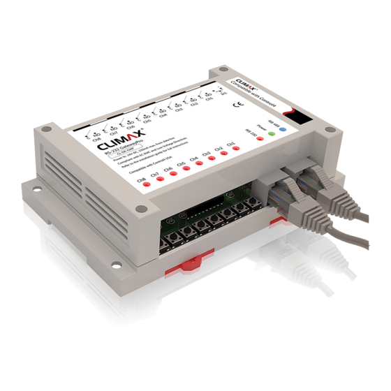
1. Screw holes
2. Power connectors
3. Contact input connector
(sensor)
4. Output connectors
5. Rail moun ng clips
6. Channel LEDs
7. Status LEDs
8. Control bu ons (1-8)
9. RS-232 jack
10. RS-485 jack
1
7
10
5
9
3
#3
#2
#1
#3
#2
#1
4
INSTALLATION GUIDE
RS-232 GatewayPro
12V-24V DC (24V DC is recommended)
Input Voltage
Input Current
C-Bus
RS-232
I/O Connec ons
Output
Input
1
Rail Mounting
RS-232 GatewayPro is designed to be installed on a standard
35 mm wide DIN rail (EN 50022, BS 5584).
Hook the module from the top, pull down the rail moun ng
clips, push the module to the rail and release the rail
moun ng clips.
1
3
2
Screw Mounting
Screw the module to any surface through 4 corner screw
holes.
Compatible with Control4 USA
2
version 1.0.7
(CL-DR-GWP)
210mA (for 24V DC)
1 X RJ45
1 X RJ45
8 relay channel-8A per channel
X
(rising-cage 5mm screw terminals)
1 digital dry contact input
X
(rising-cage 5mm screw terminals)
Advertisement

Related Manuals for Climax GatewayPro CL-DR-GWP


Summary of Contents for Climax GatewayPro CL-DR-GWP
- Page 1 INSTALLATION GUIDE version 1.0.7 1. Screw holes 2. Power connectors 3. Contact input connector (sensor) 4. Output connectors RS-232 GatewayPro 5. Rail moun ng clips (CL-DR-GWP) 6. Channel LEDs 12V-24V DC (24V DC is recommended) Input Voltage 7. Status LEDs Compatible with Control4 USA Input Current 210mA (for 24V DC)
- Page 2 Module’s LEDs When GatewayPro is not connected to any other Climax module, the main power may be supplied as following diagram. RS-485: This LED flashes if the module receives valid data packets and will remain “on” for 5 seconds when the module is receiving invalid data packet from other devices in same C-Bus network.
Need help?
Do you have a question about the GatewayPro CL-DR-GWP and is the answer not in the manual?
Questions and answers