Advertisement
Quick Links
Enable/disable Autosave
If autosave funcon is acv ated, reconnecng main power will set all outputs to the last status
(before power outage).
In order to enable/disable autosave follow steps below consecuv ely and uninterruptedly:
1. Disconnect the main power. Hold bu on #1 & #2 simultaneously (bu on's and LED's number
sequence is considered from right to le. as shown in following picture) .
2. Reconnect the main power. Release bu on #2 a er LEDs #1 to #4 flashed. Then release bu on
#1 a er LEDs #1 and #2 flashed. Power LED will start flashing quickly.
3. Press bu on #2, 4 mes.
4. To disable/enable autosave mode, press bu on #1. LED #1 will display whether autosave mode is
disabled or enabled. If it is "on" the autosave mode is enable.
5. Press bu on #3 to save the module address and bu on #4 to cancel.
It is recommended to disable autosave unless it is needed to be enabled.
#4
#3
#2
#4
#3
#2
Module's LEDs
RS-485: This LED flashes if the module receives valid data packets and will remain "on" for 5
seconds when the module is receiving invalid data packet from other devices in same C-Bus
network.
In some cases, when a new module is added to C-Bus network,
"on"
for 5 seconds. This situaon must not be considered as an error.
Power:
When the module is connected to main power,
"Power LED" remains "on".
RS-232: This LED flashes if the module receives valid data packets and will remain "on" for 5
seconds when the module is receiving invalid data packet from Control4 Home Controller.
WAN: WAN LED flashes when WAN port is connected to the network switch.
LAN: LAN LED flashes when LAN port is connected to the network switch.
Serial: This LED flashes when the module sends or receives any data from RS-232 port.
Ch1 to Ch4 : Shows the status of module's relays.
Change Device Address
The device address is fixed to "1" and is not variable.
#1
Reset
#1
3
all Status LEDs might remain
all Status LEDs flash for 1 second, then
4
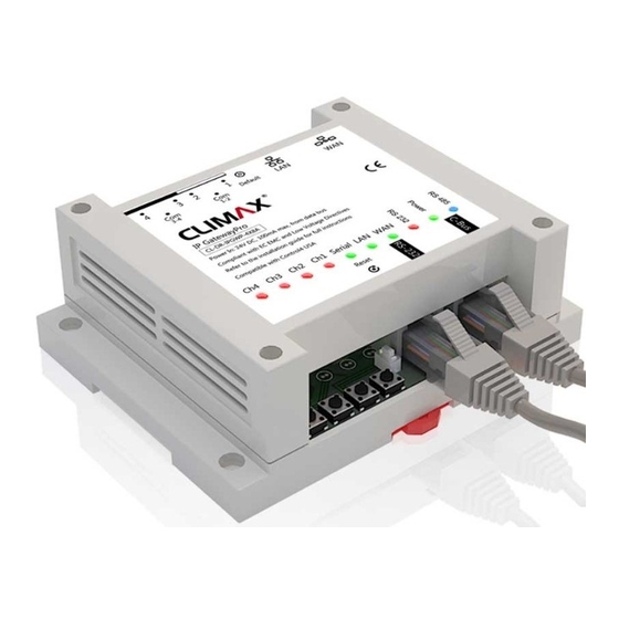
INSTALLATION GUIDE
IP GatewayPro
(CL-DR-IPGWP-4X8A)
Input Voltage
18V-24V DC (24V DC is recommended)
Input Current
C-Bus
RS-232
Output
I/O Connecons
Input
Network
1
4
5
1
4
3
2
1
Default
LAN
WAN
Com
Com
3-4
1-2
IP GatewayPro
CL-DR-IPGWP-4X8A
Serial
LAN WAN
Reset
1
6
7
8
9
2
version 1.0.2
150mA (for 24V DC)
1 X RJ45
1 X RJ45
4 X relay channel-8A per channel
(rising-cage 5mm screw terminals)
1 X digital dry contact input
(pin1 & pin2 from RS-232 port)
2 X RJ45
3
2
1
1. Screw holes
2. WAN port
3. LAN port
4. Reset network settings button
5. Output connectors
6. Channel LEDs
7. Control buttons (1-4)
8. Reset & Update Module button
9. Rail mounting clips
10. Internal Gateway status LEDs
11. RS-485 jack
12. Network status LEDs
13. RS-232 LED
1
14. RS-232 jack
10
11
12
13
14
Advertisement

Related Manuals for Climax IP GatewayPro


Summary of Contents for Climax IP GatewayPro
- Page 1 2. Reconnect the main power. Release bu on #2 a er LEDs #1 to #4 flashed. Then release bu on #1 a er LEDs #1 and #2 flashed. Power LED will start flashing quickly. IP GatewayPro (CL-DR-IPGWP-4X8A) 3. Press bu on #2, 4 mes.
- Page 2 WAN and LAN Configuraon: Follow the diagram below to use module’s internal gateway feature. IP Address Descripon IP GatewayPro Home Controller WAN Port Obtains its IP address from DHCP server Stac IP address is recommended LAN Port 192.168.16.254 It is included DHCP server: 192.168.16.0/24 6 Port Micro Hub To setup WiFi or other parameters visit www.climaxgroups.co.uk...
Need help?
Do you have a question about the IP GatewayPro and is the answer not in the manual?
Questions and answers