KEHUA TECH SPI-B Series User Manual
Pv grid-tied inverter
Hide thumbs
Also See for SPI-B Series:
- User manual (86 pages) ,
- User manual (81 pages) ,
- User manual (79 pages)
Table of Contents
Advertisement
Advertisement
Table of Contents
Troubleshooting

Related Manuals for KEHUA TECH SPI-B Series


Summary of Contents for KEHUA TECH SPI-B Series
- Page 1 PV Grid-tied Inverter SPI-B Series (75K-150K) User Manual...
- Page 2 Copyright © Kehua Data Co., Ltd. 2021. All rights reserved. No part of this document may be reproduced or transmitted in any form or by any means without prior written consent of Kehua Data Co., Ltd. Trademarks and Permissions and other Kehua trademarks are trademarks of Kehua Data Co., Ltd. All other trademarks and trade names mentioned in this document are the property of their respective holders.
- Page 3 PV Grid-tied Inverter SPI-B Series (75K-150K) User Manual Foreword Foreword Summaries Thank you for choosing the PV grid-tied inverter (hereinafter referred to as inverter)! This document gives a description of the inverter, including appearance, features, working principles, installation, electrical connection, operation, maintenance and storage, etc.
- Page 4 PV Grid-tied Inverter SPI-B Series (75K-150K) User Manual Foreword Symbol Description Alerts you to a medium low risk hazard that could, if not avoided, result in moderate or minor injury. Alerts you to a low risk hazard that could, if not avoided, result in minor injury.
-
Page 5: Table Of Contents
PV Grid-tied Inverter SPI-B Series (75K-150K) User Manual Contents Contents 1 Safety Description......................... 1 1.1 Safety Announcements ............................. 1 1.1.1 Use Announcements ..........................1 1.1.2 PV String Protection ..........................3 1.1.3 ESD Protection ............................3 1.1.4 Grounding Requirements ........................3 1.1.5 Moistureproof Protection ........................ - Page 6 PV Grid-tied Inverter SPI-B Series (75K-150K) User Manual Contents 2.4.3 PLC Communication (Optional) ......................14 2.5 PID Function (Optional) ..........................16 3 Installation............................ 18 3.1 Installation Process ............................18 3.2 Installation Tools ............................19 3.3 Selection of Installation Site .......................... 20 3.3.1 Installation Environment ........................
- Page 7 PV Grid-tied Inverter SPI-B Series (75K-150K) User Manual Contents 5 Maintenance and Troubleshooting ..................53 5.1 Maintenance ..............................53 5.1.1 Maintenance Details and Period ......................53 5.1.2 Maintenance Guide ..........................54 5.2 Troubleshooting .............................. 56 6 Stop Running, Dismantle, Discard Inverter ................59 6.1 Stop Running ..............................
-
Page 8: Safety Description
PV Grid-tied Inverter SPI-B Series (75K-150K) User Manual 1 Safety Description 1 Safety Description This chapter mainly introduces the safety announcements. Prior to performing any work on the device, please read the user manual carefully, follow the operation and installation instructions and observe all danger, warning and safety information. - Page 9 PV Grid-tied Inverter SPI-B Series (75K-150K) User Manual 1 Safety Description There is no operational part inside the inverter. Please do not open the crust of the inverter by yourself, or it may cause electric shock. The device damage caused by illegal operation is out of the guarantee range.
-
Page 10: Pv String Protection
PV Grid-tied Inverter SPI-B Series (75K-150K) User Manual 1 Safety Description 1.1.2 PV String Protection When install PV string in daytime, it necessary to cover the PV string by light-proof material, or the PV string will generate high voltage under sunshine. If touching PV string accidently, it may cause... -
Page 11: Moistureproof Protection
PV Grid-tied Inverter SPI-B Series (75K-150K) User Manual 1 Safety Description 1.1.5 Moistureproof Protection Moisture invasion may cause inverter damage! Observe the following items to ensure the inverter works normally. When the air humidity is more than 95%, don't open the door of the inverter. -
Page 12: Measurement Under Operation
PV Grid-tied Inverter SPI-B Series (75K-150K) User Manual 1 Safety Description 1.1.8 Measurement Under Operation There exists high voltage in the device. If touching device accidently, it may cause electric shock. So, when perform measurement under operation, it must take protection measure (such as wear insulated gloves, etc.) -
Page 13: Overview
PV Grid-tied Inverter SPI-B Series (75K-150K) User Manual 2 Overview 2 Overview This chapter mainly introduces product appearance, structure, working principles and communication method, etc. 2.1 Product Intro The inverter converts the DC energy from PV string into AC energy and then feedbacks to power grid, which is suitable for the large power station grid-tied system. -
Page 14: Features
PV Grid-tied Inverter SPI-B Series (75K-150K) User Manual 2 Overview Transformer Transformer Transformer PE/N Inverter Inverter Inverter TN-S TN-C TN-C-S Transformer Transformer Inverter Inverter Figure2-2 Grid form 2.1.1 Features 1100V high voltage input, increasing efficiency and cost reduction. Full voltage adaptation, strong grid support, and adaptability to complex power grid. -
Page 15: Model Meaning
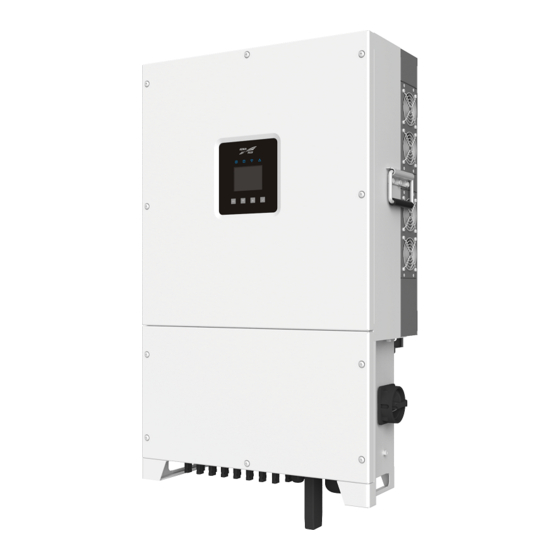
Product series mark SPI series string PV grid-tied inverter Figure2-4 Model meaning of SPII136K-BHV and SPI150K-BHV 2.2 Apperance and Structure 2.2.1 Appearance The appearance of SPI-B series (75K-150K) is as shown in Figure2-5. Ltd. All rights reserved ©Kehua Data Co.,... -
Page 16: Operation Panel
PV Grid-tied Inverter SPI-B Series (75K-150K) User Manual 2 Overview Figure2-5 Appearance 2.2.2 Operation Panel There are 5 status indicators on the front panel of the inverter, which can indicate the current working status of the inverter. The status of each indicator is shown in Table2-1. -
Page 17: Bottom Layout
PV Grid-tied Inverter SPI-B Series (75K-150K) User Manual 2 Overview Mark Color Meaning Status illustration indicator OFF: WIFI/ GPRS has been disconnected. ○ Fault indicator ON: The inverter has alarm. ON: Bluetooth has been connected with APP. Bluetooth ○ Green Flicker: Bluetooth has been disconnected with APP. - Page 18 PV Grid-tied Inverter SPI-B Series (75K-150K) User Manual 2 Overview Mark Name Remarks DC switch connects inverter with PV string. Each DC switch controls ○ DC SWITCH DC switch the PV strings in the corresponding marked area. ○ MPPT n+ /MPPT n- PV string terminal Connect PV string.
-
Page 19: Size
PV Grid-tied Inverter SPI-B Series (75K-150K) User Manual 2 Overview 2.2.4 Size Figure2-8 Size (unit: mm) 2.3 Working Principle PV strings are connected to inverter, and do the max. power point tracking for PV strings through the multi-groups of MPPT circuits inside inverter to achieve the max. power output of PV strings, and then convert the DC power into the three-phase AC power through the inverter circuit, as shown in Figure2-9 (take 9 groups of MPPT as an example) . -
Page 20: Wisesolar+App
PV Grid-tied Inverter SPI-B Series (75K-150K) User Manual 2 Overview Figure2-10 The position of RS485 communication interface …… Inverter 1 Inverter 2 Inverter N Monitoring N≤20 platform Figure2-11 RS485 communication (multiple inverters) When there is only one inverter adopts the RS485 communication, either of the two communication interfaces can be connected. -
Page 21: Plc Communication (Optional)
PV Grid-tied Inverter SPI-B Series (75K-150K) User Manual 2 Overview − Huawei application market; − APP store (iOS) . Method 2: scan the QR code below to download and install the WiseSolar+ APP according to prompting. Figure2-12 QR code of WiseSolar+ APP ○... - Page 22 PV Grid-tied Inverter SPI-B Series (75K-150K) User Manual 2 Overview Isolation Inverter 1 Grid transformer Sub-array Fiber Inverter 2 controller Inverter N Figure2-14 PLC communication connection The setting of PLC communication address is the same as that of RS485,details please see 3.6.7 Communication Connection.
-
Page 23: Pid Function (Optional)
PV Grid-tied Inverter SPI-B Series (75K-150K) User Manual 2 Overview Monitor platform Data collector Data Data collector collector Data collector Smart Data sub-array collector controller Environment Box-type Inverter monitor transformer Figure2-15 Network application scheme of smart sub-array controller 2.5 PID Function (Optional) If PID function is selected and enabled, the voltage of all PV strings to ground is greater than zero, that is to say, the voltage of all PV string to ground is positive voltage status. - Page 24 PV Grid-tied Inverter SPI-B Series (75K-150K) User Manual 2 Overview PID repair function When the inverter doesn't work, the PID function module adds the reverse voltage for PV string to repair the PV string which has occurred the PID effect.
-
Page 25: Installation
PV Grid-tied Inverter SPI-B Series (75K-150K) User Manual 3 Installation 3 Installation This chapter mainly introduces the inverter's installation, including installation process, installation preparation, handling, unpacking and checking, installation procedures, electrical connection. check the installation, etc. 3.1 Installation Process The installation process of the inverter is as shown in Figure3-1. -
Page 26: Installation Tools
PV Grid-tied Inverter SPI-B Series (75K-150K) User Manual 3 Installation 3.2 Installation Tools The recommended installation tools include but not limited to the following tools, if necessary, you can also use other auxiliary tools according to the site conditions. Tools Ltd. -
Page 27: Selection Of Installation Site
PV Grid-tied Inverter SPI-B Series (75K-150K) User Manual 3 Installation Tools The installation tools need to be insulated to avoid electric shock. 3.3 Selection of Installation Site 3.3.1 Installation Environment The installation environment has a certain influence on the service life and reliability of the inverter. -
Page 28: Installation Clearance
PV Grid-tied Inverter SPI-B Series (75K-150K) User Manual 3 Installation Figure3-2 Installation environment requirements As the inverter will make noise during working, avoid installing inverter near the residential area. Installation place will affect the safety operation, service life, performance guarantee of inverter. - Page 29 PV Grid-tied Inverter SPI-B Series (75K-150K) User Manual 3 Installation Figure3-4 Installation clearance (unit: mm) The installation height of the inverter should be convenient for viewing the status of the indicators, electrical connection, operation and maintenance, etc. The recommended clearance from the bottom of the inverter to ground is 600~800mm.
-
Page 30: Installation Carrier Requirements
PV Grid-tied Inverter SPI-B Series (75K-150K) User Manual 3 Installation Figure3-6 Back-to-back installation clearance requirements (unit: mm) 3.3.3 Installation Carrier Requirements The installation carrier of the inverter (such as wall, bracket) should meet the following requirements, as shown in Figure3-7. -
Page 31: Transporting, Unpacking And Checking
PV Grid-tied Inverter SPI-B Series (75K-150K) User Manual 3 Installation Figure3-8 Installation method As the air flow of inverter is designed for top air outlet and down air inlet, it's recommended that the inverters isn't installed horizontally. 3.4 Transporting, Unpacking and Checking 3.4.1 Transporting... - Page 32 PV Grid-tied Inverter SPI-B Series (75K-150K) User Manual 3 Installation The handles are accessory. When adopting handle transporting, install the handles to inverter. It's recommended that the inverter is transported by at least 4 people with protective equipment (such as smash-proof shoes, gloves) .
-
Page 33: Unpacking And Checking
PV Grid-tied Inverter SPI-B Series (75K-150K) User Manual 3 Installation 3.4.2 Unpacking and Checking Determine the unpacking site in advance. Normally, the unpacking site should be as close to installation position as possible. The inverter has been completely tested and strictly inspected before leaving the factory, but damage may still occur during transporting, so a detailed inspection is required after arrival. - Page 34 PV Grid-tied Inverter SPI-B Series (75K-150K) User Manual 3 Installation Step 2 Place the assembled installation holder onto the installation site, use a horizontal ruler to adjust the angle, and mark the mounting hole position on the bracket, as shown in Figure3-12.
- Page 35 PV Grid-tied Inverter SPI-B Series (75K-150K) User Manual 3 Installation Figure3-14 Drill holes (unit: mm) Step 4 Fix the installation holder to the bracket through M10*40 bolts, flat washers, spring washers and nuts, and then tighten the nuts clockwise through wrench, as shown in Figure3-15.
-
Page 36: Wall Mounting
PV Grid-tied Inverter SPI-B Series (75K-150K) User Manual 3 Installation Figure3-16 Hang the inverter onto the installation holder Do not loosen the inverter until it fixed firmly. Step 6 Fix inverter to the installation holder through the equipped M5*50 screws, as shown in Figure3-17. - Page 37 PV Grid-tied Inverter SPI-B Series (75K-150K) User Manual 3 Installation Figure3-18 Assemble installation holder Step 2 Place the assembled installation holder onto the installation site, use a horizontal ruler to adjust the angle, and mark the mounting hole position on the bracket, as shown in Figure3-19.
- Page 38 PV Grid-tied Inverter SPI-B Series (75K-150K) User Manual 3 Installation Figure3-20 Mounting hole size (unit: mm) Step 3 Use the electric drill to drill holes on the wall according to the marked position. The drilling diameter is Φ14.5mm, and the drilling depth is 55~60mm.
- Page 39 PV Grid-tied Inverter SPI-B Series (75K-150K) User Manual 3 Installation Figure3-22 Expansion bolt installation Step 5 Install the installation holder. Fix the installation holder to the expansion bolts, put on flat washers, spring washers and nuts, and then tighten the nuts clockwise through wrench, as shown in Figure3-23.
-
Page 40: Electrical Connection
PV Grid-tied Inverter SPI-B Series (75K-150K) User Manual 3 Installation Figure3-24 Hang the inverter onto the installation holder Do not loosen the inverter until it fixed firmly. Step 7 Fix inverter to the installation holder through the equipped M5*50 screws, as shown as shown in Figure3-25. -
Page 41: Wire Requirements
PV Grid-tied Inverter SPI-B Series (75K-150K) User Manual 3 Installation There may exists high voltage in the inverter. PV string exposed to sunlight will generate dangerous voltage. Do not switch on the DC switches and external AC switch until the electrical connection is completed. -
Page 42: External Grounding Connection
PV Grid-tied Inverter SPI-B Series (75K-150K) User Manual 3 Installation Wire name Wire type Recommended cross-sectional area of wire Outdoor three-core wire: 70~240mm (Max. outer Outdoor diameter<56mm) . L1/L2/ multi-core wire or Outdoor single--core wire: 70~240mm (Max. outer AC output single-core wire diameter<26mm) . - Page 43 PV Grid-tied Inverter SPI-B Series (75K-150K) User Manual 3 Installation Step 1 Strip the insulation layer of the grounding wire by crimping tool, and crimp it into the corresponding terminal, as shown in Figure3-26. Figure3-26 Grounding wire crimping diagram It is recommended to use DT or OT terminal for the external grounding wire.
-
Page 44: Ac Output Wiring
PV Grid-tied Inverter SPI-B Series (75K-150K) User Manual 3 Installation The grounding of inverter mustn't connect with the grounding of the lighting rod of the building where the inverter installs. It should separate them, or the lightning stroke will damage inverter, as shown in Figure3-28. - Page 45 PV Grid-tied Inverter SPI-B Series (75K-150K) User Manual 3 Installation Table3-2 The recommended specification of the three-pole switch Model Rated voltage (V) Rated current (A) SPI75K-B, SPI80K-B, SPI90K-B, SPI100K-B, SPI110K-B, SPI125K-B SPI136K-BHV, SPI150K-BHV If multiple inverters share a switch, the switch selection depends on the total current.
- Page 46 PV Grid-tied Inverter SPI-B Series (75K-150K) User Manual 3 Installation The apparent power of inverter can not exceed the transformer power. The max. AC current of all paralleled inverters must be considered. As a part of the PV grid-connected power generation system, the carrying capacity of the transformer must be considered when the system fails(including system short-circuit, grounding fault, voltage drop, etc.) .
- Page 47 PV Grid-tied Inverter SPI-B Series (75K-150K) User Manual 3 Installation Figure3-30 Dismantle the right cover of the wiring box A limiting lever is designed inside the wiring box. After the wiring cover is opened, fix the limiting lever (as shown in Figure3-31) to facilitate the wiring operation.
- Page 48 PV Grid-tied Inverter SPI-B Series (75K-150K) User Manual 3 Installation Figure3-32 Connect the AC output wire The torque of the nylon cable gland in the "AC OUTPUT" is about 15~19N· m. The insulation baffles among terminals can not be dismantled.
-
Page 49: Internal Grounding Connection
PV Grid-tied Inverter SPI-B Series (75K-150K) User Manual 3 Installation When leaving the factory, the wire outlet is sealed. Before wiring, puncture it by tool. Please connect the AC output wire based on the local country requirements. Step 3 Tighten the nylon cable gland in the "AC OUTPUT"... -
Page 50: Pv String Input Wiring
PV Grid-tied Inverter SPI-B Series (75K-150K) User Manual 3 Installation 3.6.6 PV String Input Wiring PV string exposed to sunlight will generate dangerous voltage. If the PV string input wires are reverse connected and the "DC SWITCH" has be set to ON position, do not immediately operate the "DC SWITCH"... - Page 51 PV Grid-tied Inverter SPI-B Series (75K-150K) User Manual 3 Installation Use the DC terminals and PV connectors in the accessories for DC input wiring. There are two types of PV connectors: positive connectors and negative connectors, which respectively use positive metal terminals and negative metal terminals.
- Page 52 PV Grid-tied Inverter SPI-B Series (75K-150K) User Manual 3 Installation Figure3-37 Fix the metal terminals Step 4 Tighten the locking nuts of the positive and negative connectors to corresponding insulating shells, as shown in Figure3-38. Figure3-38 Tighten the lock nut...
- Page 53 PV Grid-tied Inverter SPI-B Series (75K-150K) User Manual 3 Installation Figure3-39 Wiring diagram (connection in the inverter side) Figure3-40 Wiring diagram (connection in the PV string side) Install PV connectors ○ Step 1 Ensure that all DC switches on the inverter (as shown in the 2 of Figure2-7) are set OFF position.
- Page 54 PV Grid-tied Inverter SPI-B Series (75K-150K) User Manual 3 Installation Step 2 Check whether the polarity of the PV string is correct, and ensure that the open-circuit voltage in any case does not exceed the max. input voltage of the inverter 1100V.
-
Page 55: Communication Connection
PV Grid-tied Inverter SPI-B Series (75K-150K) User Manual 3 Installation If any PV connector on the inverter is not connected to PV string, block it with original plug. ----End 3.6.7 Communication Connection Step 1 Plug RS485 communication wire into the RS485 port on the communication board, as shown in Figure3-45. - Page 56 PV Grid-tied Inverter SPI-B Series (75K-150K) User Manual 3 Installation Figure3-46 SW1 position When multiple inverters communicates, the dial switch SW2 on the communication board of first and last inverters on the communication link must be set to the ON position.
-
Page 57: Check The Installation
PV Grid-tied Inverter SPI-B Series (75K-150K) User Manual 3 Installation Step 2 After wiring, tighten the nylon cable gland in the "COM1/COM2", block the communication wiring holes by fireproofing mud, and install the right cover of the wiring box. ----End 3.7 Check the Installation... -
Page 58: Startup And Shutdown
PV Grid-tied Inverter SPI-B Series (75K-150K) User Manual 4 Startup and Shutdown 4 Startup and Shutdown This chapter mainly introduces how to start and shut down the inverter. 4.1 Check Before Startup Before starting inverter at the first time, please check the following items. -
Page 59: Shut Down Inverter
PV Grid-tied Inverter SPI-B Series (75K-150K) User Manual 4 Startup and Shutdown After ensure the inverter is normal, start inverter according to following steps. Step 1 Switch on the DC switches on the inverter and the project site. When the PV string provides enough startup voltage, PV string indicator will be on. -
Page 60: Maintenance And Troubleshooting
PV Grid-tied Inverter SPI-B Series (75K-150K) User Manual 5 Maintenance and Troubleshooting 5 Maintenance and Troubleshooting This chapter mainly introduces the maintenance and troubleshooting. 5.1 Maintenance If any maintenance service is needed, please contact the after-sale service centre of Kehua Company, otherwise, Kehua Company will not undertake the responsibility and guarantee for the loss caused by self-operation. -
Page 61: Maintenance Guide
PV Grid-tied Inverter SPI-B Series (75K-150K) User Manual 5 Maintenance and Troubleshooting Item Check method Maintenance period maintain it in time. Wire Inlet Check if the wire inlet holes are sealed up completely, Every year hole if not, seal them with fireproof mud. - Page 62 PV Grid-tied Inverter SPI-B Series (75K-150K) User Manual 5 Maintenance and Troubleshooting Fan maintenance Before maintenance, shut down the inverter and disconnect all power input. Wait for 30min at least, after the inner capacitor discharge completely and check that there is no voltage and current in the inverter by the detection equipment, the maintenance can be done.
-
Page 63: Troubleshooting
PV Grid-tied Inverter SPI-B Series (75K-150K) User Manual 5 Maintenance and Troubleshooting Figure5-2 Loosen the wiring of fan module Step 4 Pull out the fan module, clean the fan by brush or cleaner or replace damaged fan. Figure5-3 Pull out fan module Step 5 Install the fan module in reversed order and lock the screws, restart the inverter. - Page 64 PV Grid-tied Inverter SPI-B Series (75K-150K) User Manual 5 Maintenance and Troubleshooting Table5-2 Troubleshooting list Fault information Solution Check whether the safety regulations of the inverter meet the Grid voltage requirements of the local grid connection and check the voltage of the abnormal local power grid.
- Page 65 PV Grid-tied Inverter SPI-B Series (75K-150K) User Manual 5 Maintenance and Troubleshooting Fault information Solution Check whether the radiator of the inverter is blocked, and check Inner whether the ambient temperature of the inverter is too high or too over-temperature low.
-
Page 66: Stop Running, Dismantle, Discard Inverter
PV Grid-tied Inverter SPI-B Series (75K-150K) User Manual 6 Stop Running, Dismantle, Discard Inverter 6 Stop Running, Dismantle, Discard Inverter This chapter introduces the dispose way for stop running, dismantling, discarding the inverter. 6.1 Stop Running Normally, the inverter don't need to be shut down, but when maintenance, it is necessary to shut down the inverter. -
Page 67: Dismantle The Inverter
PV Grid-tied Inverter SPI-B Series (75K-150K) User Manual 6 Stop Running, Dismantle, Discard Inverter 6.2 Dismantle the Inverter After the connection among inverter and grid and PV string is completely disconnected and wait for 30mins at least, ensure that the inner capacitor discharge completely and check that there is no voltage and current in the inverter by the detection equipment, and then the inverter can be dismantled. -
Page 68: Package, Transportation, Storage
PV Grid-tied Inverter SPI-B Series (75K-150K) User Manual 7 Package, Transportation, Storage 7 Package, Transportation, Storage This chapter mainly introduces the package, transportation and storage. 7.1 Package The package of product is carton. When packing, pay attention to the placing direction requirements. -
Page 69: A Technical Specifications
PV Grid-tied Inverter SPI-B Series (75K-150K) User Manual A Technical Specifications Technical Specifications A.1 SPI75K-B, SPI80K-B, SPI90K-B and SPI100K-B Items SPI75K-B SPI80K-B SPI90K-B SPI100K-B DC input Max. input voltage 1100V Min. input voltage/startup voltage 200V/250V Rated input voltage 600V MPPT voltage range... - Page 70 PV Grid-tied Inverter SPI-B Series (75K-150K) User Manual A Technical Specifications Items SPI75K-B SPI80K-B SPI90K-B SPI100K-B Max. output apparent power 75kVA 88kVA 99kVA 110kVA Rated output current 108.3A 115.5A 129.9A 144.4A Max. output current 108.3A 127A 142.9A 158.8A Rated grid voltage...
- Page 71 PV Grid-tied Inverter SPI-B Series (75K-150K) User Manual A Technical Specifications Items SPI75K-B SPI80K-B SPI90K-B SPI100K-B Heat dissipation way Smart forced wind-cooling Max. operation altitude 4000m (>3000m decrease rate power) Display LED, Bluetooth +APP Communication RS485/GPRS (optional) / WIFI (optional)
- Page 72 PV Grid-tied Inverter SPI-B Series (75K-150K) User Manual A Technical Specifications Items SPI110K-B SPI125K-B SPI136K-BHV SPI150K-BHV Rated output current 158.8A 180.5A 145.4A 160.4A Max. output current 174.7A 198.5A 159.9A 176.4A Rated grid voltage 3/N/PE, 230V/400V 3/PE, 310V/540V Grid voltage range...
- Page 73 PV Grid-tied Inverter SPI-B Series (75K-150K) User Manual A Technical Specifications Items SPI110K-B SPI125K-B SPI136K-BHV SPI150K-BHV Max. operation altitude 4000m (>3000m decrease rate power) Display LED, Bluetooth +APP Communication RS485/GPRS (optional )/WIFI (optional ) DC terminal type AC terminal type OT terminal (Max.
-
Page 74: B Torque Specifications
PV Grid-tied Inverter SPI-B Series (75K-150K) User Manual B Torque Specifications Torque Specifications Fastener type Connection material Steel-Steel (N· m) 0.7~1 1.8~2.4 4~4.8 18~23 34~40 60~70 119~140 The connection material means the material of screw and thread hole. Ltd. All rights reserved ©Kehua Data Co.,... -
Page 75: C Quality Assurance
PV Grid-tied Inverter SPI-B Series (75K-150K) User Manual C Quality Assurance Quality Assurance If the device fault in guarantee period, Kehua Data Co., Ltd. (hereinafter referred to as Kehua Company) will maintenance it free or replace new product. Evidence In guarantee period, user needs to show the purchase invoice of the product, and the trademark on the product must be clearly visible, or, Kehua Company have right to refuse the quality assurance. - Page 76 PV Grid-tied Inverter SPI-B Series (75K-150K) User Manual C Quality Assurance Damage caused by abnormal nature environment. If the fault is caused by above situation and user requires to maintain it, we can provide paid maintenance service after our service organization decided.
-
Page 77: D Acronyms And Abbreviations
PV Grid-tied Inverter SPI-B Series (75K-150K) User Manual D Acronyms and Abbreviations Acronyms and Abbreviations Alternating Current Liquid Crystal Display Light-emitting Diode Maximum Power Point Tracking MPPT Protective Earthing Photovoltaic RS485 Recommend Standard485 Ltd. All rights reserved ©Kehua Data Co.,... - Page 78 PV Grid-tied Inverter SPI-B Series (75K-150K) User Manual D Acronyms and Abbreviations Universal Serial Bus Ltd. All rights reserved ©Kehua Data Co.,...
- Page 79 4402-03569 003...
Need help?
Do you have a question about the SPI-B Series and is the answer not in the manual?
Questions and answers