Table of Contents
Advertisement
Advertisement
Table of Contents
Troubleshooting

Subscribe to Our Youtube Channel
Related Manuals for KEHUA TECH SPI-B-H Series SPI175K-B-H


Summary of Contents for KEHUA TECH SPI-B-H Series SPI175K-B-H
- Page 1 String PV Grid-tied Inverter SPI-B-H Series (175K-250K) User Manual...
- Page 3 Copyright © KehuaHengshengCo.,Ltd.2020.All rights reserved. No part of this document may be reproduced or transmitted in any form or by any means without prior written consent of KehuaHengshengCo.,Ltd. Trademarks and Permissions and other Kehua trademarks are trademarks of KehuaHengsheng Co., Ltd. All other trademarks and trade names mentioned in this document are the property of their respective holders.
- Page 4 String PV Grid-tied Inverter SPI-B-H Series (175K-250K) Foreword User Manual Foreword Summaries Thank you for choosing the SPI-B series (175K-250K) string PV grid-tied inverter(Hereinafter referred to as inverter)! This document gives a description of inverter, including the appearance, features, working principles, installation, electrical connection, operation, maintenance and storage, etc.
- Page 5 String PV Grid-tied Inverter SPI-B-H Series (175K-250K) User Manual Foreword Symbol Description Alerts you to a potentially hazardous situation that could, if not avoided, result in equipment damage, data loss, performance deterioration, or unanticipated results. Anti-static prompting. Be care electric shock prompting. Provides a tip that may help you solve a problem or save time.
-
Page 6: Table Of Contents
String PV Grid-tied Inverter SPI-B-H Series (175K-250K) Contents User Manual Contents 1 Safety Description......................... 1 1.1 Safety Announcements ............................. 1 1.1.1 Use Announcements ..........................1 1.1.2 PV Array Protection ..........................3 1.1.3 ESD Protection ............................3 1.1.4 Grounding Requirements ........................4 1.1.5 Moistureproof Protection ........................ - Page 7 String PV Grid-tied Inverter SPI-B-H Series (175K-250K) User Manual Contents 2.4.3 WIFI/GPRS Communication (Optional) ....................13 2.4.4 PLC Communication (Optional) ......................14 3 Installation............................ 15 3.1 Installation Process ............................15 3.2 Installation Tools ............................15 3.3 Selection of installation site ........................... 17 3.3.1 Installation Environment ........................
- Page 8 String PV Grid-tied Inverter SPI-B-H Series (175K-250K) Contents User Manual 5 Maintenance and Troubleshooting ..................48 5.1 Maintenance ..............................48 5.2 Troubleshooting .............................. 49 6 Package, Transportation, Storage ..................... 52 6.1 Package ................................52 6.2 Transportation ..............................52 6.3 Storage ................................52 A Technical Specifications ......................
-
Page 9: Safety Description
String PV Grid-tied Inverter SPI-B-H Series (175K-250K) User Manual 1Safety Description 1 Safety Description This chapter mainly describes the safety announcements. Prior to performing any work on the device, please read the user manual carefully, follow the operation and installation instructions and observe all danger, warning and safety information, which is to avoid human injury and device damage by irregular operations. - Page 10 String PV Grid-tied Inverter SPI-B-H Series (175K-250K) 1Safety Description User Manual There is no operational part inside device. Please do not open the crust of device by yourself, or it may cause electric shock. The device damage caused by illegal operation is out of the guarantee range.
-
Page 11: Pv Array Protection
String PV Grid-tied Inverter SPI-B-H Series (175K-250K) User Manual 1Safety Description No liquid or other objects are allowed to enter the cabinet. In case of fire, please use dry power fire extinguisher. If using liquid fire extinguisher, it may cause electric shock. -
Page 12: Grounding Requirements
String PV Grid-tied Inverter SPI-B-H Series (175K-250K) 1Safety Description User Manual 1.1.4 Grounding Requirements High leakage risk! Device must be grounded before performing electrical connection. The grounding terminal must be connected to ground. When install device, it must be grounded first. When dismantle device, the grounding wire must be removed at last;... -
Page 13: Measurement Under Operation
String PV Grid-tied Inverter SPI-B-H Series (175K-250K) User Manual 1Safety Description The configuration of PV array, grid level, grid frequency, etc. must meet the technical requirements of inverter. Grid-tied generation should be allowed by the local power supply department and the related operation should be performed by professionals. -
Page 14: Overview
String PV Grid-tied Inverter SPI-B-H Series (175K-250K) 2Overview User Manual 2 Overview This chapter mainly describes product appearance, structure, working principle and communication method, etc. 2.1 Product Intro The inverter converts the DC energy from PV array into AC energy and then feedbacks to power grid, which is suitable for the large power station grid-tied system. -
Page 15: Features
String PV Grid-tied Inverter SPI-B-H Series (175K-250K) User Manual 2Overview Transformer Inverter Figure2-2 Grid mode 2.1.1 Features Adopts the efficient three level high frequency conversion technology and advanced full digital control technology. Good power grid adaptability and excellent power quality. ... -
Page 16: Apperance And Structure
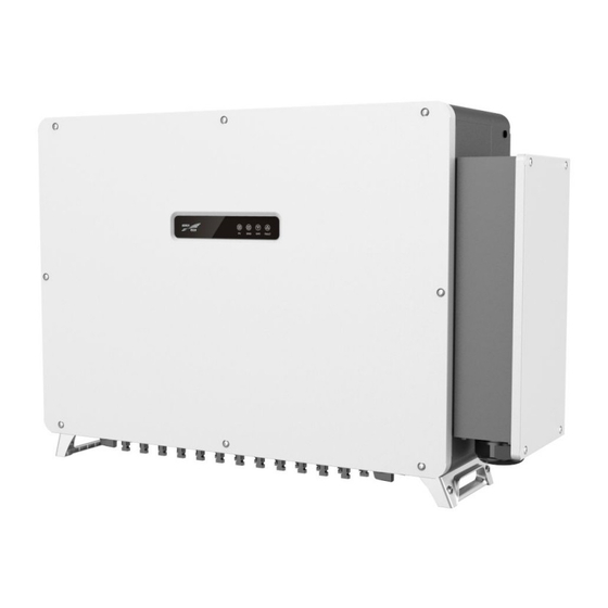
String PV Grid-tied Inverter SPI-B-H Series (175K-250K) 2Overview User Manual 2.2 Apperance and Structure 2.2.1 Apperance The appearance of SPI-B-H series string PV grid-tied inverter is as shown in Figure2-4. Figure2-4 Appearance 2.2.2 Operation Panel There are 4 status indicators on the front panel of the inverter, which can indicate the current working status of the inverter. -
Page 17: Floor Layout
String PV Grid-tied Inverter SPI-B-H Series (175K-250K) User Manual 2Overview Mark Color Meaning Status illustration ON: Grid-tied status Grid connection Flicker: Inverter stay in decrease rated power ○ Green indicator output status OFF: No grid-tied status ON: WIFI/ GPRS has been connected WIFI/GPRS ○... - Page 18 String PV Grid-tied Inverter SPI-B-H Series (175K-250K) 2Overview User Manual Mark Name Remarks Connection switch between inverter and ○ DC SWITCH DC switch PV string. Balance the pressure difference between ○ Breathable valve inside and outside of the machine. WIFI/GPRS stick interface ○...
-
Page 19: Dimension
String PV Grid-tied Inverter SPI-B-H Series (175K-250K) User Manual 2Overview 2.2.4 Dimension Figure2-7 Inverter dimensions (unit: mm) 2.3 Working Principle The PV string input is connected to the inverter, and the maximum power point of the PV string is tracked through the internal 12 groups of MPPT circuits to achieve the maximum power output of the photovoltaic string, and then the conversion of DC power to three-phase AC power is realized through the inverter circuit. -
Page 20: Rs485 Communication
String PV Grid-tied Inverter SPI-B-H Series (175K-250K) 2Overview User Manual Figure2-9 Ethernet communication interface location …… Inverter Inverter Inverter Router Monitoring platform Figure2-10 Ethernet monitoring (multiple inverters) 2.4.2 RS485 Communication RS485 communication (the interface location is shown in Figure2-11) is mainly used for local area network monitoring, which can realize the remote monitoring. -
Page 21: Wifi/Gprs Communication (Optional)
String PV Grid-tied Inverter SPI-B-H Series (175K-250K) User Manual 2Overview Figure2-11 RS485communication interface location …… Inverter 1 Inverter 2 Inverter N Monitoring N≤20 platform Figure2-12 RS485 communication (multi-unit inverters) When only one inverter communicates via RS485, choose one of the two communication interfaces to connect. -
Page 22: Plc Communication (Optional)
String PV Grid-tied Inverter SPI-B-H Series (175K-250K) 2Overview User Manual Smart phone Inverter (include GPRS) Internet Router Inverter (include WIFI) Computer monitor Figure2-13 WIFI/GPRS monitoring solution 2.4.4 PLC Communication (Optional) If the inverter is equipped with PLC communication, Kehua sub-array controller needs to be configured. -
Page 23: Installation
String PV Grid-tied Inverter SPI-B-H Series (175K-250K) User Manual 3Installation 3 Installation This chapter mainly introduces the inverter's installation, including installation process, installation preparation, handling, unpacking and checking, installation procedures, electrical connection. check the installation ,etc. 3.1 Installation Process The installation process of inverter is as shown in Figure3-1. Start Installation preparation... - Page 24 String PV Grid-tied Inverter SPI-B-H Series (175K-250K) 3Installation User Manual Tools Ltd. All rights reserved ©Kehua Hengsheng Co.,...
-
Page 25: Selection Of Installation Site
String PV Grid-tied Inverter SPI-B-H Series (175K-250K) User Manual 3Installation Tools The installation tools need to be insulated to avoid electric shock. Multimeter range≥1500Vdc. Wrech specification: T30. 3.3 Selection of installation site 3.3.1 Installation Environment The use environment has a certain influence on the service life and reliability of the equipment. Therefore, please pay attention to avoid using the equipment in the following working environment. -
Page 26: Installation Clearance
String PV Grid-tied Inverter SPI-B-H Series (175K-250K) 3Installation User Manual Figure3-2 Installation environment requirements As the operation of inverter will produce noise pollution, thus avoid installing them near residential areas as much as possible. Choose the best installation location for the inverter, which plays a very important role in its safe operation, service life, performance guarantee, etc. - Page 27 String PV Grid-tied Inverter SPI-B-H Series (175K-250K) User Manual 3Installation Figure3-4 Installation clearance The installation height of the inverter should be easy to check the status of the indicator lights, and it is convenient for electrical connection, operation and maintenance, etc. ...
-
Page 28: Installation Method
String PV Grid-tied Inverter SPI-B-H Series (175K-250K) 3Installation User Manual Figure3-6 Back-to-back installation space requirements (unit: mm) 3.3.3 Installation method It is recommended to install the inverter vertically or obliquely backwards (with an angle of ≤15° from the vertical plane). It cannot be tilted forward, inverted installed. Figure3-7 Illustration of installation method Because the air duct of the inverter is designed for the downward air inlet and the upper air outlet, in order to ensure the normal operation of the inverter, it is not recommended to install it horizontally. -
Page 29: Handling, Unpacking And Checking
String PV Grid-tied Inverter SPI-B-H Series (175K-250K) User Manual 3Installation Figure3-8 Installation carrier requirements 3.4 Handling, Unpacking and Checking 3.4.1 Handling Before installation, the inverter needs to be transported to the selected installation site. When transporting, you can choose to carry the handle or the ring according to the scene. Handle Figure3-9 Curry by handle The handle is a random accessory. - Page 30 String PV Grid-tied Inverter SPI-B-H Series (175K-250K) 3Installation User Manual When handling device, move it carefully to avoid impact or fall. During the transportation process, always pay attention to the gravity center of the inverter, do not suddenly put down or lift it up. ...
-
Page 31: Unpacking And Checking
String PV Grid-tied Inverter SPI-B-H Series (175K-250K) User Manual 3Installation 3.4.2 Unpacking and Checking Determine the unpacking site in advance. Normally, it's better that the unpacking site is close to installation position. The inverter has been completely tested and strictly inspected before leaving the factory, but damage may still occur during transportation, so a detailed inspection is required after arrival. - Page 32 String PV Grid-tied Inverter SPI-B-H Series (175K-250K) 3Installation User Manual Step 2 Place the assembled wall mount at the installation point, use a horizontal ruler to adjust the angle, and mark the position of the hole on the bracket, as shown in Figure3-12. Please ensure that the wall mount is level to ensure that the mounting holes are consistent and aligned.
- Page 33 String PV Grid-tied Inverter SPI-B-H Series (175K-250K) User Manual 3Installation Figure3-14 Drilling holes Step 4 Fix the wall mount to the bracket, use M10*40 bolts, put on flat washers, spring washers and nuts, and then tighten the nuts clockwise with a wrench to fix the wall mount to the bracket, as shown in Figure3-15.
- Page 34 String PV Grid-tied Inverter SPI-B-H Series (175K-250K) 3Installation User Manual Figure3-16 Hang the inverter on the wall bracket After confirming that the inverter is fixed firmly, the operator can release the equipment. Step 6 Use the screws M5*50 in the accessories to fix both sides of the inverter on the wall bracket, as shown in Figure3-17.
-
Page 35: Wall Mounting
String PV Grid-tied Inverter SPI-B-H Series (175K-250K) User Manual 3Installation 3.5.2 Wall mounting Step 1 Use four M4*10 combination bolts in the random accessories to fix the wall mount assembly through the connecting rod, as shown in Figure3-18. Figure3-18 Assembling the wall mount Step 2 Place the assembled wall mount at the installation point, use a spirit level to adjust the angle, and mark the location of the hole on the wall, as shown in Figure3-19. - Page 36 String PV Grid-tied Inverter SPI-B-H Series (175K-250K) 3Installation User Manual You can also directly mark the location of the hole according to the size of the mounting hole of the wall mount (see Figure3-8). Figure3-20 Mounting hole size(unit: mm) Step 3 According to the marked position, use a hammer drill to drill holes in the wall.
- Page 37 String PV Grid-tied Inverter SPI-B-H Series (175K-250K) User Manual 3Installation Figure3-22 Expansion bolt installation diagram Step 5 Install the wall mount. Fix the wall mount to the expansion bolts, cover with flat washers, spring washers and nuts, and then tighten the nuts clockwise with a wrench to fix the wall mount to the wall, as shown in Figure3-23.
- Page 38 String PV Grid-tied Inverter SPI-B-H Series (175K-250K) 3Installation User Manual Figure3-24 Hang the inverter on the wall bracket After confirming that the inverter is fixed firmly, the operator can release the equipment. Step 7 Use the screws M5*50 in the accessories to fix both sides of the inverter on the wall bracket, as shown in Figure3-25.
-
Page 39: Electrical Connection
String PV Grid-tied Inverter SPI-B-H Series (175K-250K) User Manual 3Installation 3.6 Electrical Connection 3.6.1 Safety Precautions During electrical operation, professionals must wear protective equipment. High voltage may exist in the inverter. Photovoltaic strings exposed to sunlight will generate dangerous voltage. ... -
Page 40: External Ground Connection
String PV Grid-tied Inverter SPI-B-H Series (175K-250K) 3Installation User Manual Table3-1 Wire requirements Name Type Recommended wire diameter(mm ) 1500V and above PV PV string input cable cables cable : 70~240 Outdoor three/four core Outdoor multi-core (Maximum outer diameter<56mm); AC output cable cable or single-core Outdoor single-core cable:70~300 (Maximum cable... - Page 41 String PV Grid-tied Inverter SPI-B-H Series (175K-250K) User Manual 3Installation Since the inverter is with no transformer, it is required that the positive and negative poles of the photovoltaic string cannot be grounded, otherwise the inverter will not operate normally. ...
-
Page 42: Ac Output Wiring
String PV Grid-tied Inverter SPI-B-H Series (175K-250K) 3Installation User Manual Two external ground terminals are reserved at the bottom of the inverter, at least one of them should be selected for grounding. In order to improve the anti-corrosion performance of the ground terminal, it is recommended to apply anti-rust paint on the outside of the ground terminal for protection after the bottom line is installed. - Page 43 String PV Grid-tied Inverter SPI-B-H Series (175K-250K) User Manual 3Installation Each inverter is equipped with an independent four-pole circuit breaker on the AC side to ensure that the inverter is safely disconnected from the power grid. Recommended circuit breaker rated voltage is 800V, rated current is 250A.
- Page 44 String PV Grid-tied Inverter SPI-B-H Series (175K-250K) 3Installation User Manual Figure3-30 Open the wiring cover A limited position rod is designed on the inside of the door panel of the wiring box. After the door panel is opened, the limit rod needs to be fixed (as shown in Figure Figure3-31) to facilitate the wiring operation.
- Page 45 String PV Grid-tied Inverter SPI-B-H Series (175K-250K) User Manual 3Installation AC L1, L2 and L3 respectively, and crimp to the terminal, and then connect to the AC output terminal block, as shown in Figure3-32. Figure3-32 Connect the AC output cable 说明...
-
Page 46: Internal Ground Connection
String PV Grid-tied Inverter SPI-B-H Series (175K-250K) 3Installation User Manual Figure3-33 AC cable entry requirements (unit:mm) When leaving the factory, one end of the cable seal ring outlet is in a sealed state. Before connecting the cable, the end of the cable seal ring outlet needs to be punctured by a tool ... -
Page 47: Pv String Input Wiring
String PV Grid-tied Inverter SPI-B-H Series (175K-250K) User Manual 3Installation Figure3-34 Connect internal ground The torque used when tightening the externally forced cable fixing head of the internal ground wire is about 10~13N•m. 3.6.6 PV string input wiring Pay attention to safety before electrical connection, the PV string will produce dangerous voltage when exposed to sunlight. - Page 48 String PV Grid-tied Inverter SPI-B-H Series (175K-250K) 3Installation User Manual If you accidentally reverse the DC input line and the "DC SWITCH" is set to the "ON" position, do not immediately operate the "DC SWITCH" and the positive and negative connectors, otherwise it may cause equipment damage.
- Page 49 String PV Grid-tied Inverter SPI-B-H Series (175K-250K) User Manual 3Installation Figure3-35 Schematic diagram of stripping DC input wiring (Unit:mm) It is recommended to use red for positive cables and black for negative cables to avoid wiring errors. If other colors are used, please confirm the corresponding relationship when crimping each cable to the connector.
- Page 50 String PV Grid-tied Inverter SPI-B-H Series (175K-250K) 3Installation User Manual Figure3-38 Tighten the lock nut ----End Install PV connectors ○ Step 1 Confirm that all DC switches on the inverter (location is shown as 2 in Figure3-39) are in the OFF state.
-
Page 51: Wifi/Gprs Communication Connection(Optional)
String PV Grid-tied Inverter SPI-B-H Series (175K-250K) User Manual 3Installation Figure3-41 Connect DC terminal ----End 3.6.7 WIFI/GPRS Communication Connection(Optional) If there has optional component WIFI/GPRS stick, insert the equipped WIFI/GPRS stick into the WIFI/GPRS port to do the internet monitoring, as shown in Figure3-42. Figure3-42 WIFI/GPRS communication connection When connecting, pay attention to the limit, and don't insert it wrong. -
Page 52: Com.communication Connection
String PV Grid-tied Inverter SPI-B-H Series (175K-250K) 3Installation User Manual 3.6.8 COM.communication connection COM. communication includes Ethernet communication and RS485 communication. Step 1 Loosen the external forced cable fixing head at "COM.", and then pass the communication cable through the external forced cable fixing head. Step 2 Connect the communication wire ... - Page 53 String PV Grid-tied Inverter SPI-B-H Series (175K-250K) User Manual 3Installation Connect the RS485 communication wires to the RS485 interface on the communication board, as shown in Figure3-44, and connect the other end to the monitoring platform. Figure3-44 RS485 connection When connecting the terminals, be careful not to press the insulation layer of the communication cable, otherwise it may cause poor contact.
-
Page 54: Check The Installation
String PV Grid-tied Inverter SPI-B-H Series (175K-250K) 3Installation User Manual Figure3-45 SW1 position When multiple inverters are communicating, all the DIP switches SW3 on the communication boards of the two inverters on the communication link must be switched to the ON position. The communication address of the inverter must not conflict. -
Page 55: Startup And Shutdown
String PV Grid-tied Inverter SPI-B-H Series (175K-250K) User Manual 4Startup and Shutdown 4 Startup and Shutdown This chapter mainly introduces how to start and shut down the inverter. 4.1 Start Inverter Step 1 Switch on the DC switch in the inverter and the DC switch in the project site. When the PV array provides enough startup voltage, PV connection indicator will be on. -
Page 56: Maintenance And Troubleshooting
String PV Grid-tied Inverter SPI-B-H Series (175K-250K) 5Maintenance and Troubleshooting User Manual 5 Maintenance and Troubleshooting This chapter mainly describes the maintenance and troubleshooting. 5.1 Maintenance When maintenance or wiring, it should switch off DC switch. In order for the inverter to work in the best condition, it is recommended to maintain it regularly. ... -
Page 57: Troubleshooting
String PV Grid-tied Inverter SPI-B-H Series (175K-250K) User Manual 5Maintenance and Troubleshooting When the power generation value displayed on the monitoring platform is inconsistent with the external measurement device, the user can correct the power generation value of the monitoring platform according to the Kehua communication protocol. - Page 58 String PV Grid-tied Inverter SPI-B-H Series (175K-250K) 5Maintenance and Troubleshooting User Manual Fault information Deal way center. If the fault persists, please contact your local agency or service Relay failure center. Check whether the radiator of the inverter is blocked, and check Radiator whether the ambient temperature of the inverter is too high or too over-temperature...
- Page 59 String PV Grid-tied Inverter SPI-B-H Series (175K-250K) User Manual 5Maintenance and Troubleshooting If the inverter has an alarm mentioned in Table5-1, please shut down inverter(refer to 4.2 Shut Down Inverter), 5 minutes later, restart the inverter (refer to 4.1 Start Inverter). If the alarm status is not removed, please contact our local agency or service center.
-
Page 60: Package, Transportation, Storage
String PV Grid-tied Inverter SPI-B-H Series (175K-250K) 6Package, Transportation, Storage User Manual 6 Package, Transportation, Storage This chapter mainly describes the package, transportation and storage. 6.1 Package The package of product is carton. When packing, pay attention to the placing direction requirements. One side of carton, it should print warning icons, including keep dry, handle with care, up, stacking layer limit, etc. -
Page 61: A Technical Specifications
String PV Grid-tied Inverter SPI-B-H Series (175K-250K) User Manual A Technical Specifications Technical Specifications A.1 SPI175K-B-H Items Min. Typical Max. Illustration Max. PV input voltage(Vdc) 1500 MPPT working voltage with 1300 full load(Vdc) PV connected/ MPPT tracking 18/9 DC current of each route(A) PV input power(kW) Startup voltage(V) Grid features... - Page 62 String PV Grid-tied Inverter SPI-B-H Series (175K-250K) A Technical Specifications User Manual Items Min. Typical Max. Illustration Grid-tied China efficiency 98.4% Grid-tied current harmonic Under full-load Power factor range (ahead) (lag) Current DC component <631mA Output current (A) 139.3 IP66 Protection grade(IP) With no transformer, the input cannot...
- Page 63 String PV Grid-tied Inverter SPI-B-H Series (175K-250K) User Manual A Technical Specifications A.2 SPI200K-B-H Items Min. Typical Max. Illustration Max. PV input voltage(Vdc) 1500 MPPT working voltage with 1300 full load(Vdc) PV connected/ MPPT tracking 24/12 DC current of each route(A) PV input power(kW) Startup voltage(V) Grid features...
- Page 64 String PV Grid-tied Inverter SPI-B-H Series (175K-250K) A Technical Specifications User Manual Items Min. Typical Max. Illustration Output current (A) 158.8 IP66 Protection grade(IP) With no transformer, the input cannot connected with Isolation type No isolation ground, or the grounding output must with isolation...
- Page 65 String PV Grid-tied Inverter SPI-B-H Series (175K-250K) User Manual A Technical Specifications Items Min. Typical Max. Illustration PV connected/ MPPT tracking 24/12 DC current of each route(A) PV input power(kW) 247.5 Startup voltage(V) Grid features Output power(kW) 247.5 Rated grid voltage(Vac) 800V(3P3W) Settable (If it is necessary to set Grid voltage range(Vac)
- Page 66 String PV Grid-tied Inverter SPI-B-H Series (175K-250K) A Technical Specifications User Manual Items Min. Typical Max. Illustration ground, or the grounding output must with isolation transformer. Heat dissipation way Smart wind-cooling install <75±2dBA@1m Noise noise-sensitive environment Display way LED indicator Communication port RS485/ Ethernet/ WIFI(optional)/ GPRS(optional)/ PLC(optional) Operation temperature(℃)
- Page 67 String PV Grid-tied Inverter SPI-B-H Series (175K-250K) User Manual A Technical Specifications Items Min. Typical Max. Illustration Startup voltage(V) Grid features Outputpower(kW) Rated grid voltage(Vac) 800V(3P3W) Settable (If it is necessary to Grid voltage range(Vac) parameter, please contact the manufacturer.) Settable (If it is necessary to Frequency range(Hz) 50.5...
- Page 68 String PV Grid-tied Inverter SPI-B-H Series (175K-250K) A Technical Specifications User Manual Items Min. Typical Max. Illustration Display way LED indicator RS485/ Ethernet/ WIFI(optional)/ GPRS (optional) Communication port PLC(optional) Operation temperature (℃) Storage temperature (℃) Relative humidity 100% Atmosphere (kPa) When the altitude exceeds 4000 Altitude (m)
-
Page 69: B Acronyms And Abbreviations
String PV Grid-tied Inverter SPI-B-H Series (175K-250K) User Manual B Acronyms and Abbreviations Acronyms and Abbreviations Alternating Current Direct Current Liquid Crystal Display Light-emitting Diode MPPT Maximum Power Point Tracking Protective Earthing Photovoltaic Ltd. All rights reserved ©Kehua Hengsheng Co.,... - Page 70 String PV Grid-tied Inverter SPI-B-H Series (175K-250K) B Acronyms and Abbreviations User Manual RS485 Recommend Standard485 Ltd. All rights reserved ©Kehua Hengsheng Co.,...
- Page 71 4402-00000001...
Need help?
Do you have a question about the SPI-B-H Series SPI175K-B-H and is the answer not in the manual?
Questions and answers