Subscribe to Our Youtube Channel
Summary of Contents for Safe Fleet PRIME DESIGN masterack VRR CE
-
Page 2: Contents Overview
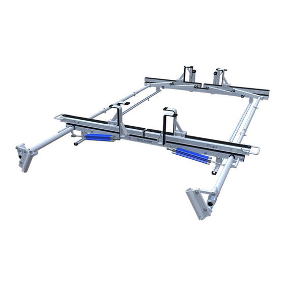
CONTENTS OVERVIEW 1—FBM-0045 ............(Qty 1) Channels w/Hardware Channels (2X) M8 Bolt (6X) End Caps (4X) Brackets (4X) Nylon Washer (6X) Foam Gasket (6X) Flex Channel Connector (6X) 2—Rear Crossbar Assembly ........(Qty 1) 3—Front Crossbar Assembly ........ (Qty 1) - Page 3 4—Rear Drive Shaft ..........(Qty 1) RH, B4 Version, 46.00” 5—Handle Latch Assembly ........(Qty 1) Right Hand 6—Connecting Bar ..........(Qty 2) 24.00” 7—Front Drive Shaft ..........(Qty 2) B Version, 35.75” 8—Z Post ............... (Qty 4) Adjustable, 7.25”...
- Page 4 FBM-0045 Install Channels into roof Channel groove as shown CHANNELS TO ROOF Position Channels as shown below in Fig.1 F r o R i g R e a Install fasteners into factory Slide Channel Connectors roof rail mounting locations. into Channels as shown Torque to 150 in-lbs Fig.
- Page 5 RIGHT ROTATION ASSEMBLY SEQUENCE 3/16 CROSSBARS CROSSBAR ADJUSTMENT F r o Even Front Even Even Rear Even Torque to 90 in-lbs...
-
Page 6: Rear Drive Shaft
REAR DRIVE SHAFT CYLINDER HARDWARE Torque to 80 in-lbs Torque to 90 in-lbs CONNECTING BAR FRONT DRIVE SHAFT Torque to 90 in-lbs... - Page 7 CONNECTING BAR FASTENERS Z POSTS SEE QUICK START GUIDE FOR ADJUSTMENTS Torque to 90 in-lbs L POSTS SEE QUICK START GUIDE FOR ADJUSTMENTS Torque to 70 in-lbs...
- Page 8 LEFT ROTATION ASSEMBLY SEQUENCE 10/16 REAR DRIVE SHAFT CYLINDER HARDWARE 10.1 10.2 Torque to 80 in-lbs Torque to 90 in-lbs...
- Page 9 CONNECTING BAR FRONT DRIVE SHAFT 12.1 12.2 11.1 12.3 11.2 12.4 Torque to 90 in-lbs CONNECTING BAR FASTENERS Z POSTS SEE QUICK START GUIDE FOR ADJUSTMENTS 14.1 14.1 14.2 Torque to 90 in-lbs...
- Page 10 L POSTS CYLINDER ADJUSTMENT SEE QUICK START GUIDE FOR ADJUSTMENTS 15.1 15.1 Adjust the Cylinder Flow 15.2 Control Screw to allow approximately 3 seconds Torque to 70 in-lbs time for the ladder to glide down when operating the loaded Ladder Rack. DRIVE SHAFT SEALING 17.1 17.2...


Need help?
Do you have a question about the PRIME DESIGN masterack VRR CE and is the answer not in the manual?
Questions and answers