
Related Manuals for Get Packed GPAS-158

Summary of Contents for Get Packed GPAS-158
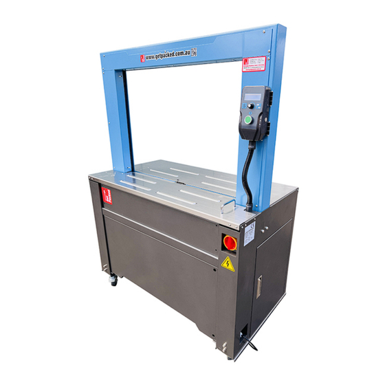
- Page 1 AUTOMATIC STRAPPING MACHINE MODEL: EXS-158 PLUS GPAS-158 GPAS-158 OPERATION MANUAL OPERATION MANUAL OPERATION MANUAL 2022-2-16...
- Page 2 EC Declaration of Conformity According to the following EU Directives: ⚫ Machinery Directive: 2006/42/EC ⚫ Low Voltage Directive: 2014/35/EU ⚫ Electromagnetic Compatibility Directive: 2014/30/EU EXTEND GREAT INTERNATIONAL CORP. Add: 20F, No. 309, Sec. 2, Taiwan Blvd., Taichung, Taiwan R.O.C Tel: +886-4-2326-5568 Fax: +886-4-2326-2268 Declare that the machines mentioned hereafter: ◎Product: Strapping Machine...
-
Page 3: Table Of Contents
1 GENERAL SAFETY INSTRUCTIONS Basic Operation ........................5 Basic Safety Precautions ....................5 Safety Instructions Governing Specific Operational Phases ..........6 Warning of Electrical Dangers .................... 7 Grounding Instructions Shall Include the Following ............8 Before Operating ........................ 9 During Operation ....................... 9 After operating ........................ - Page 4 4 OPERATING THE MACHINE Main Page ......................... 24 Operation Mode Page ...................... 25 Setting Page ........................26 Service Mode Page ......................27 Factory Setting Page ......................28 Counter Page ........................28 5 ADJUSTMENT Strap amount in the Pool Box ..................29 Pool Feed pressure &...
-
Page 5: General Safety Instructions
1. GENERAL SAFETY INSTRUCTIONS 1.1 Basic Operation ⚫ The manual and the safety remarks are to be read before use. The operator manual should be kept with the machine at all times. Intervals for maintenance and inspections are to be adhered to. ⚫... -
Page 6: Safety Instructions Governing Specific Operational Phases
1.3 Safety Instructions Governing Specific Operational Phases ⚫ Avoid any operation mode that might be unsafe. ⚫ All necessary precautions to ensure that the machine is only used being in a safe and reliable state are to be taken. The machine is only to be operated if all protective and safety devices, including removable safety devices, emergency shut-off equipment, noise-protection elements and exhaust systems are in right place and fully functional. -
Page 7: Warning Of Electrical Dangers
1.4 Warning of Electrical Dangers ⚫ Immediately remove power to the machine in case of trouble in the electrical system. ⚫ Replace a fuse with one with the same style and ratings; pay particular attention to matching the specified current. ⚫... -
Page 8: Grounding Instructions Shall Include The Following
1.5 Grounding Instructions Shall Include the Following ⚫ This product must be grounded. In the event of an electrical short circuit, grounding reduces the risk of electric shock. This product is equipped with a cord that has a grounding wire and an appropriate grounding plug. The plug must be plugged into an outlet that is properly installed and grounded in accordance with all local codes and ordinances. -
Page 9: Before Operating
1.6 Before Operating ⚫ Verify that the power line voltage is correct. ⚫ The machine must be properly grounded to avoid a shock hazard. All wiring must be in accordance with local wiring standards. ⚫ The strapping machine can only be operated with polypropylene (P.P.) strapping; do not use polyester (PET) strapping or polyethylene (PE) cord strap. -
Page 10: Signs
1.9 Signs Caution! Electric Shock Hazard. Caution! Hot Surface. Caution! Moving Parts Can Crush Hand. Caution! Pinch Point Entanglement Caution! Blade. Cutting of Fingers or Hand Wear Eye Protection Refer to Operator Manual... -
Page 11: Machine Information
2. MACHINE INFORMATION 2.1 Areas of Application This plastic strapping machine can be used for a wide range of applications where the minimum package width is at least 70mm, and the minimum height is 20mm. This machine is particularly suitable for heavy packaged goods as well as printed products, boxes, etc. -
Page 12: Environmental Information
2.2 Environmental Information The strapping machine shall be installed in the following conditions: ⚫ Supply voltage: +-10% nominal supply voltage ⚫ Source frequency: +-10% nominal frequency ⚫ Ambient temperature: 5°C - 40°C (41℉-104℉). ⚫ Relative humidity: not exceed 35~85%RH ⚫ Please provide a suitable illumination around the machine for safety operation. -
Page 13: Machine Description
2.3 Machine Description ⚫ Automatic strapping machine for polypropylene (PP) strapping material. ⚫ Strap width 9-12mm adjustable. ⚫ High efficiency heater plate. ⚫ Front & rear table are hinged with quick release structure. ⚫ Loop ejection in case of strapping cycle without package. ⚫... -
Page 14: Safety Devices
2.4 Safety Devices DANGER! Operate the machine only when all safety devices are at their place and are functioning correctly. The machine has been constructed in accordance with the applicable legal regulations. The machine is reliable in operation. Nevertheless the machine may constitute a danger if it is operated in improper or undue condition. - Page 15 The machine is turned on when it is connected to AC power and the main power switch, located on the front operating panel, is placed in the ON position. After approximately 1 minute, the heating element will reach its operating temperature and the machine will be ready for use.
-
Page 16: Technical Specification
2.5 Technical Specification 2.5.1 Electrical Specification System Configuration L1+N+PE (GROUND) L1+N+PE (GROUND) Nominal Power 0.72 kW 0.72 kW Rated Current 3.1 A 6.5 A Rated Voltage 200V/220V/230V/240V 100V/110V Rated Frequency 50 Hz 60 Hz Type of Current AC- single phase AC –... -
Page 17: Identification Data Of The Machine
STRAP WIDTH 9mm/12mm ONLY (BY ADJUSTMENT) STRAP THICKNESS 0.45mm – 0.7mm Coil diameter: 200mm (230mm/280mm as option) STRAP COIL Width: 190mm-200mm MACHINE SIZE 1130mm (L)* 619mm (W) * 1535mm (H) NET WEIGHT 180 Kg TENSION RANGE 50 N – 650 N SPEED 37 STRAP/MIN TABLE HEIGHT... -
Page 18: Before Operating The Machine
3. BEFORE OPERATING THE MACHINE 3.1 Shipping The machine is delivered as a transport unit. The machine is loaded onto a wooden pallet with Polyester strap secured. Outside with carbon box also with Polyester strap secured. 3.2 Transportation & Unload Machine from Pallet The machine needs to be secured well on wooden pallet. -
Page 19: Installation
3.3 Installation a. Remove packaging material and check if the machine is complete without any transportation damage b. Remove cushion material inside corners of the arch. c. After positioning the machine, do make sure lock brake of casters (two front casters with brake) Note: when moving the machine again, do remember to unlock the brake of casters, then relocate and lock again. -
Page 20: Operation Space
3.4 Operation Clearance Keep the area (A) and (B) free for the operator. The area (A) is necessary for operating strapping machine. The area (B) is necessary for changing the strap. -
Page 21: Operation Elements
3.5 Operation Elements a. Main Power Switch: Provide the machine with Power. Switch to ”I” for ON to operate the machine; switch to “—“ for OFF to shut power off. b. LCD Display: Indicate condition and error message of the machine c. -
Page 22: Auto Threading Of Polypropylene Strap
3.6 Auto Threading of Polypropylene Strap 3.6.1 Strap Specification Material: Polypropylene Strap Width: 9mm/12mm only adjustment Thickness: 0.45mm-0.7mm (any strap outside this range, please contact EXTEND for further studying) Core diameter: 200mm (230mm and 280mm as option) Core width: 190mm-200mm Strap with excessive chamber (5mm with 200cm length) cannot be used. - Page 23 3.6.3 Auto Thread Function a. Turn on the main power switch b. Press “Start Button” to make machine self-detect c. Make sure LCD display showing “REMOVE LAST STRAP, LOAD NEW STRAP” d. Make sure no previous strap left in the chute e.
-
Page 24: Operating The Machine
4. OPERATING THE MACHINE There are many functions of the machine in LCD Display, showing as below 4.1 Main Page TENSION Main page shows current situation of machine and also is able to adjust tension setting. (A) Shows current strapping mode (operation mode): ➢... -
Page 25: Operation Mode Page
4.2 Operation Mode Page OPERATION MODE Operation Mode allows operator to change strapping mode. (C) Shows strapping mode and detail setting of mode. Operator could press Potentiometer, then the (C) will twinkle then it’s allowed to change to different mode ➢... -
Page 26: Setting Page
4.3 Setting Page SETTING (D) Shows current setting of machine, operator could change the setting through the Potentiometer. ➢ COOLING TIME _ _ S: This is strap welding cooling timer adjust. If you have big tension with hard package, longer cooling time could help you with better seal on strap. Press Potentiometer →... -
Page 27: Service Mode Page
4.4 Service Mode Page SERVICE MODE SERVICE MODE PASSWORD:_ _ _ _ For service only, this function allows technician go detail check (password protect, please contact for password), you could rotate the Potentiometer to select manual function then press Start Button to run. ➢... -
Page 28: Factory Setting Page
4.5 Factory Setting Page FACTORY SETTING PASSWORD: _ _ _ _ This is for factory setting usage only, change the setting will have no warranty protect. 4.6 Counter Page COUNTER COUNTS _ _ _ _ _ _ _ _ This machine is equipped with strap cycle counter, furthermore it is allowed to be reset on this counter. -
Page 29: Adjustment
5. ADJUSTMENT 5.1 Strap amount in the Pool Box The recommended strap amount in Pool Box will be 2 of full arch size, it will be sufficient for 3-5 strap cycles. (Depend on package size, fewer cycles for larger package size) Note: Excessive strap amount stored in Pool Box will cause feed problem (too curved) Note: Insufficient strap amount stored in Pool Box will cause short feed Note: Strap stored in Pool Box overnight will make itself too curved and have chance to... -
Page 30: Pool Feed Pressure & Gap
5.2 Pool Feed pressure & gap The machine is well set for the Pool Feed pressure and gap. It might need some adjustment when you have smooth strap on this machine. Note: Excessive pressure for Pool Feed Roller might cause strap squeezed then jammed Note: Insufficient pressure for Pool Feed Roller might cause insufficient strap amount in Pool Box. -
Page 31: Feeding / Refeeding Pressure & Gap
5.3 Feeding / Refeeding pressure & gap The machine is well set for Feeding/Refeeding pressure and gap. It might needs some adjustment when you have smooth strap or different thickness on this machine, to avoid short feed or feed jam issue happened. Note: Excessive or insufficient gap between Feed Rollers might cause failure for auto threading and 2 try feeding... -
Page 32: Tension
5.4 Tension The machine is well set for Tension. It might needs some adjustment when you have smooth strap or different thickness on this machine, or you have different application. Note: Excessive Tension might cause damage on strap then jammed Note: Excessive Tension might also cause Tension Roller touch strap in zero position then having Feeding or Refeeding problem. -
Page 33: Brush In Arch
5.5 Brush in Arch The machine is well set for Brush in Arch to avoid strap floating or flipping. Note: Brush in Arch may need some adjustment for special package shape or different application/different strap width. The adjustment of Brush: Release screws to adjust brush ➢... -
Page 34: Change Between 9Mm And 12Mm
5.6 Change between 9mm and 12mm The machine is able to change between 9mm and 12mm strap only adjustment. Note: Tools Needed Change between 9mm and 12mm: a. Open front door and remove 5 nuts to take off the Pool Box Cover... - Page 35 b. Put necessary spacer in the Pool Area: Long spacer + short spacer = 12mm application Long Spacer = 9mm application (remember to fix the short spacer outside in case it’s missing) c. Open the arch and release 3 screws for Feeding Bandway...
- Page 36 d. Adjust the plate to touch strap then pulling outward about 1mm more e. Adjust the Arch Bandway Right to touch strap then pulling outward about 1mm more...
- Page 37 f. Adjust front table cover, there are two screws on each side, loose the screws then move front table forward or backward to fit with strap, then pulling out around 0.5mm more. Brush in Arch g. Adjust brush, follow instruction in EXS-158 PLUS operation manual 5.5...
-
Page 38: Trouble Shooting
6. TROUBLE SHOOTING Error List: LCD Display will show error situation for this machine, at the same time technician could open the electric box check LED lights on main PCB in detail. ➢ ERROR (M313), LCD FAIL (J6) It means there’s no signal between LCD panel board and main PCB. Please check the connection/wiring is good and tight, or replace new LCD panel board. - Page 39 ➢ ERROR (M307), SHORT FEED It means the machine already feeds in maximum time but still not able to arrive the actuator. ◼ Please make sure strap in Pool Box is not curved too much ◼ Please make sure Feed Roller are in good gap and pressure adjustment (please Feeding / Refeeding pressure &...
-
Page 40: Maintenance
7. MAINTENANCE Note: Before doing any maintenance or service, please do switch off the main power on the machine, then wait about 5 minutes to cool down the heater plate. Weekly Maintenance: ➢ Use air gun to clean dust from the machine, especially following clean dust from following structures: ◼... - Page 41 ◼ Sliding table Unit & Separator Unit ➢ Lubrication on moving mechanism , especially lubricate on following structures: ◼ Clamps Unit ◼ Sliding table Unit & Separator Unit Note: Do not lubricate on any bandway or guide where transport strap. Monthly Maintenance: ➢...
-
Page 42: Electric Wiring Diagram & Part
8. ELECTRIC WIRING DIAGRAM & PART... - Page 44 PART NO. DESCRIPTION Q’TY P0307-010001600 POWER SUPPLY P0306-020000100 RELAY P0306-030000100 RELAY SEAT P0316-050000100 RELAY FIX PLATE P0309-01001090B MAIN BOARD P0305-030001100 FUSE 8A P0305-020001000 FUSE SEAT P0305-020001100 FUSE COVER P0305-030000100 FUSE 2A (For 220V) P0305-030001000 FUSE 4A (For 110V) F3,4,5 P0305-020001000 FUSE SEAT P0305-020001100 FUSE COVER...
-
Page 46: Part List
9. PART LIST... - Page 47 FIG. 1-1 CASTER UNIT FIGURE 1-1 CASTER UNIT PART NUMBER Description P1107-0004500 CASTER P1107-0004600 CASTER WITH BRAKE P1101-0506025AN SCREW M6*25L P1103-0206Z SPRING WASHER φ6 P1103-010612N WASER φ6*12*1t...
- Page 48 FIG. 2-1 POOL FEED UNIT...
- Page 49 FIGURE 2-1 POOL FEED UNIT PART NUMBER Description P02-033970B POOL FEED SEAT P1104-076201ZZ0 BEARING P0501-0018300 POOL MOTOR 220V P0501-0018400 POOL MOTOR 110V P02-0340400 POOL FEED DRIVING ROLLER P02-034030A POOL FEED DRIVEN ROLLER P1104-020608ZZ1 BEARING P1105-0222B C-RING, R-22 P02-0340100 POOL FEED LOWER GUIDE 9-12mm P1101-0504016AN SCREW M4*16 P1101-0505020AN...
- Page 50 FIGURE 2-1 POOL FEED UNIT PART NUMBER Description P1102-0106AN NUT M6 P1104-020625ZZ0 BEARING, 625ZZ P1101-0506016AN SCREW M6*16 P1108-010404020G KEY 4*4*20 P1101-0905012AN SCREW M5*12 P02-0339810 POOL SPACER 9-12mm P1103-010409N WASHER ψ4*9 P1109-0204018G PIN 4*18 P1101-0504012AN SCREW M4*12 P01-0558600 DETECTION PLATE P01-0555600 DETECTION PLATE FIXER P0319-S15835 PROX SWITCH (3METER)
- Page 51 FIG. 3-1 TABLE PIN UNIT FIGURE 3-1 TABLE PIN UNIT PART NUMBER Description P01-0550100 PIN SEAT P02-0349100 TABLE PIN P1102-0106AN NUT M6 P1103-010613N WASHER φ6*13 P1201-0000200 SPRING P01-0585200 PICK P1103-0206Z SPRING WASHER φ6...
- Page 52 FIG. 4-1 FRONT TABLE UNIT FIGURE 4-1 FRONT TABLE UNIT PART NUMBER Description P01-054762A FRONT TABLE COVER P08-0002800 TABLE ROLLER P1112-0002900 TABLE HANDLE P1101-0905012AN SCREW M5*12 TABLE PIN UNIT – FIG 3-1 P1101-0604006AN SCREW M4*6 P1101-0405016AN SCREW M5*16...
- Page 53 FIG. 5-1 REAR TABLE UNIT FIGURE 5-1 REAR TABLE UNIT PART NUMBER Description P01-054772A REAR TABLE COVER P08-0002800 TABLE ROLLER P1112-0002900 TABLE HANDLE TABLE PIN UNIT – FIG 3-1 P1101-0604006AN SCREW M4*6 P1101-0405016AN SCREW M5*16 P1101-0905012AN SCREW M5*12...
- Page 54 FIG. 6-1 AUTO THREADING UNIT...
- Page 55 FIGURE 6-1 AUTO THREADING UNIT PART NUMBER Description P02-0363100 AUTO FEED GUIDE ASSEM P0501-0018500 AUTO THREAD MOTOR P01-0552900 AUTO THREAD MOTOR BRACKET P1101-0504012AN SCREW M4*12 P1102-0104AN NUT, M4 P1102-0110AZ NUT, M10 P02-0372600 ADJUST RING P01-0553000 FIXED RING P1201-0010900 AUTO THREADING SPRING P02-0340900 ADJUSTING FIXER P06-0064800...
- Page 56 FIG. 7-1 POOL GUIDE ROLLER UNIT FIGURE 7-1 POOL GUIDE ROLLER UNIT PART NUMBER Description P01-0552800 POOL GUIDE ROLLER BRACKET P02-0341600 POOL GUIDE ROLLER P1104-020626ZZ0 BEARING, 626ZZ P1101-0506055AN SCREW M4*12 P1102-0106BZ NUT, M6 P1103-010612N WASHER, φ6*12*1t...
- Page 57 FIG. 8-1 ARCH UNIT...
- Page 58 FIGURE 8-1 ARCH UNIT PART NUMBER Description CONTROL BOX UNIT – FIG 9-1 ARCH (850*600MM) ARCH SUPPORT UNIT – FIG 11-1 EJECT PIN UNIT – FIG 12-1 UPPER ARCH OPEN UNIT FIG 31-1 P01-054712A ARCH COVER (RIGHT) P01-0549620 BRUSH FIX PLATE (RIGHT) P13-0001100 BRUSH (RIGHT) P1101-0104010AZ...
- Page 59 PARTS LIST. FIGURE 8-1 ARCH UNIT PART NUMBER Description P1103-010409N WASHER φ4*9 P1103-0204Z SPRING WASHER φ5 P1102-0104BZ HEX NUT, M4 P1101-0605010AN SCREW M5*10 P1101-0405012AN SCREW M5*12 P1201-0011400 SPRING...
- Page 60 FIG. 9-1 CONTROL BOX UNIT...
- Page 61 FIGURE 9-1 CONTROL BOX UNIT PART NUMBER Description P06-0063000 CONTROL BOX P0309-02000260A LCD BOARD P0309-010014300 VR BOARD P0313-010005700 START BUTTON P1110-010000300 HINGE P0401-0006000 CABLE CONNECT P1106-020000100 REAR MAGNET P1101-0605008AN SCREW M4*10 P1106-020000800 SIDE MAGNET KNOB RN-99F,∮6.4 P1113-000100A P1102-0105AN NUT, M5 P1101-0405012AN SCREW M5*12 P1101-0303010AZ...
- Page 62 FIG. 10-1 INNER ARCH UNIT...
- Page 63 FIGURE 10-1 INNER ARCH UNIT PART NUMBER Description P01-054751C INNER ARCH BRACKET P06-0064000 9~12MM BANDWAY P06-0064300 9~12MM BANDWAY CORNER P06-0064200 9~12MM BANDWAY P06-0064240 9~12MM BANDWAY P06-0064100 9~12MM BANDWAY P02-0339100 BANDWAY CONNECTING GUIDE (L) P02-033920A BANDWAY CONNECTING GUIDE (R) P01-0554400 ARCH LEFT GUIDE PLATE P01-055450A ARCH RIGHT ADJUSTING PLATE P01-055460B...
- Page 64 FIG. 11-1 ARCH SUPPORT UNIT FIGURE 11-1 ARCH SUPPORT UNIT PART NUMBER Description P01-0611900 SUPPORT BRACKET P1103-010512N WASHER φ5*12 P1104-020635ZZ2 BEARING 635ZZ P1101-0505020AN SCREW M5*20 P1103-0205Z SPRING WASHER φ5 P1102-0105AZ NUT M5...
- Page 65 FIG. 12-1 EJECT PIN UNIT FIGURE 12-1 EJECT PIN UNIT PART NUMBER Description P1101-0606016AN SCREW M6*16 P02-0347800 SUPPORT P02-034790A EJECT PIN P1102-0103BZ NUT, M3 P01-0555400 PIN FIXER P1101-0905012AN SCREW M5*12 P1103-010306B5Z WASHER M3*6*0.5...
- Page 66 FIG. 13-1 MACHINE ASSEMBLE...
- Page 67 FIGURE 13-1 MACHINE ASSEMBLE PART NUMBER Description MACHINE FRAME UNIT (W 850) CASTER UNIT – FIG 1-1 DISPENSER UNIT – FIG 15-1 POOL FEED UNIT – FIG 2-1 P01-0575500 POOL LEVER STOPPER P01-054954A POOL COVER P0319-S15834 PROXIMITY SWITCH QL-05N P01-0041700 PROXIMITY SWITCH PLATE P1202-0000100 SPRING...
- Page 68 FIGURE 13-1 MACHINE ASSEMBLE PART NUMBER Description POOL GUIDE ROLLER UNIT – FIG 7-1 P01-0553200 POOL FEED ADJUSTING PLATE P01-0553300 POOL ADJUST PLATE SEALER UNIT – FIG 20-1 ARCH UNIT – 850*600 P1101-0605010AN SCREW M5*10 AUTO THREADING UNIT – FIG 6-1 P02-0340510 POOL GUIDE 850 P01-0549200...
- Page 69 FIG. 14-1 POOL LEVER UNIT FIGURE 14-1 POOL LEVER UNIT PART NUMBER Description P02-0348700 POOL LEVER SHAFT P1104-0310201 BEARING CB1020 P02-0352720 POOL LEVER P02-0352600 POOL LEVER FIXER P1101-0104006AZ SCREW M4*6 P1102-0104AN HEX NUT M4 P01-0575400 POOL LEVER SUPPORT PLATE P1101-1005045AZ SCREW M5x45L P1102-0105AN HEX NUT M5...
- Page 70 FIG. 15-1 DISPENSER UNIT...
- Page 71 FIGURE 15-1 DISPENSER UNIT PART NUMBER Description P1124-0001600 SLIDE P01-055190D DISPENSER SEAT P02-033930A DISPENSER SHAFT P1104-026304ZZ0 BEARING, 6304ZZ P02-0339400 BRAKE ARM SPACER P01-0041200 PULLEY BRACKET P06-000680C PULLEY P1101-0504030AN SCREW M4*30 P1103-0204Z SPRING WASHER φ4 P1101-0506016AN SCREW M6*16L P1102-0106AN NUT M6 P1202-0000400 SPRING P01-0551700...
- Page 72 FIGURE 15-1 DISPENSER UNIT PART NUMBER Description P01-0552200 PLATE P1101-0504025AN SCREW M4*25 P1102-0104AZ NUT M4 P1101-0606010AN SCREW M6*10 P01-0552300 BELT FIX PLATE P0902-0008900 V-BELT P1101-0504035AN SCREW M4*35 P1103-010409N WASHER ψ4 P1101-0906016AN SCREW M6*16L P06-000690A CUSHION CAP P1103-010612N WASHER φ6 P1103-0206Z SPRING WASHER φ6 P01-0585300 PULL HANDLE...
- Page 73 FIG. 16-1 SIDE DOOR UNIT FIGURE 16-1 SIDE DOOR UNIT PART NUMBER Description P01-0548100 SIDE DOOR P1112-0000500 SIDE DOOR HANDLE P01-0042000 HANDLE FIXER P0311-030000100 (OPTION) CIRCUIT BREAKER KEY P1101-0104010AZ SCREW M4*10 P1101-0504008AN SCREW M4*8...
- Page 74 FIG. 17-1 FEEDING UNIT...
- Page 75 FIGURE 17-1 FEEDING UNIT PART NUMBER Description P02-033670B FEED SEAT P02-033810A FEED BANDWAY P02-0337900 TENSION DRIVING ROLLER P01-0558200 FEED SPACER PLATE P02-0337700 GUIDE BLOCK LEFT P02-0337800 GUIDE BLOCK RIGHT P02-035100A FEED BANDWAY COVER P1104-026002ZZ3 BEARING P0319-S15838 BRAKE P1104-026202ZZ2 BEARING P0701-0004800 TENSION GEAR P1108-010505010G KEY 5*5*10...
- Page 76 FIGURE 17-1 FEEDING UNIT PART NUMBER Description P1104-020635ZZ2 BEARING P02-0336900 TENSION CAM LEVEL P1101-0504020AN SCREW M4*20 P1103-0204Z SPRING WASHER φ4 P1102-0104AN NUT M4 P1103-0205Z SPRING WASHER φ5 P1103-010510N WASHER φ5 P1101-0505040AN SCREW M5*40 P01-0559200 FAN BRACKET P01-055880B ADJUSTMENT FIXING PLATE P1103-010612N WASHER φ6*12*1t P1103-0206Z...
- Page 77 FIGURE 17-1 FEEDING UNIT PART NUMBER Description P01-0559000 PLATE P02-033800A FEED DRIVING ROLLER P1101-0906016AN SCREW M6*16 P1108-010505012G KEY 5*5*12 P02-0096300 BRAKE WHEEL P0303-020000100 FAN COVER P0503-0016900 M2 REDUCER MOTOR 110V 50HZ P0503-0017000 M2 REDUCER MOTOR 110V 60HZ P0503-0017100 M2 REDUCER MOTOR 220V 50HZ P0503-0017200 M2 REDUCER MOTOR 220V 60HZ P02-0310400...
- Page 78 FIG. 18-1 FEED DRIVEN UNIT FIGURE 18-1 FEED DRIVEN UNIT PART NUMBER Description P02-033820A FEED ECCENTRIC SHAFT P1103-010412N WASHER φ4*12 P02-0338400 FEED DRIVEN ROLLER P1101-0904008AN SCREW M4*8...
- Page 79 FIG. 19-1 TENSION UNIT...
- Page 80 FIGURE 19-1 TENSION UNIT PART NUMBER Description P02-0337100 TENSION SEAT P02-0310400 BEARING P1101-0504020AN SCREW M4*20 P1103-0204Z SPRING WASHER φ4 P1102-0104AN NUT M4 P1202-0012700 SPRING P1103-010409N WASHER ψ4*9 P0701-0004800 TENSION GEAR P02-0337200 TENSION DRIVEN ROLLER P1104-026000ZZ0 BEARING P02-033730A TENSION ARM SHAFT P1103-011016B4S WASHER ψ10*ψ16*0.4 P1108-010505010G...
- Page 81 FIG. 20-1 SEALER UNIT...
- Page 82 FIGURE 20-1 SEALER UNIT PART NUMBER Description P1101-0504016AN SCREW M4*16 P1101-0504016AN SCREW M4*16 P1102-0104AZ NUT M4 P02-0333700 SEALER SEAT P02-033380B SLIDING TABLE SUPPORT RIGHT P02-033390B SLIDING TABLE SUPPORT LEFT P02-033400C SLIDING TABLE CAM UNIT – FIG 21-1 SEPERATOR UNIT – FIG 23-1 P01-055650A SLIDING TABLE SPRING BRACKET P06-0065300...
- Page 83 FIGURE 20-1 SEALER UNIT PART NUMBER Description P02-0336500 ARCH OPENER SHAFT P1103-010816N WASHERφ8*16 P1103-0208Z SPRING WASHERφ8 P1101-1008030AHZ SCREW M8*30 P0319-S15837 BRAKE P02-0096300 BRAKE WHEEL P06-0065300 CUSHION P1202-0010600 SPRING P1104-0308080 BEARING P01-055780B REFEEDING LEVER P1104-020635ZZ2 BEARING P1101-1005016AZ SCREW M5*16 P1103-0205Z SPRING WASHER φ5 P02-0337000 REFEEDING LEVER SHAFT P01-0557600...
- Page 84 FIGURE 20-1 SEALER UNIT PART NUMBER Description P06-006500A CUSHIONG M8 P1101-0508025AN SCREW M8*25 P1102-0108AZ NUT M8*12MM P01-055740A TABLE SUPPORT LEFT P1103-010512N WASHER φ5*12 P1101-0505020AN SCREW M5*20L P02-0336600 ARCH OPENER FIXER P0303-020000100 FAN COVER P1101-0104035AZ SCREW M4*35 P1103-0204Z SPRING WASHER φ4 P1102-0104AN NUT M4 P1101-0904008AN...
- Page 85 FIG. 21-1 CAM UNIT...
- Page 86 FIGURE 21-1 CAM UNIT PART NUMBER Description P02-0335400 BEARING SEAT LEFT P02-0336100 BEARING SEAT RIGHT P02-0334900 CAM SHAFT P1104-026004ZZ1 BEARING P02-0336000 CAM (HEATING) P02-0335900 CAM (END-GRIPPER) P02-0335800 CAM (WELDING CLAMP) P02-0335700 CAM (SLIDING TABLE) P02-0335600 CAM (HOLDING GRIPPER) P02-0335000 CAM (ARCH) P1105-0120B C RING S-20 P02-0335300...
- Page 87 FIG. 22-1 CLAMP SEAT UNIT...
- Page 88 FIGURE 22-1 CLAMP SEAT UNIT PART NUMBER Description P02-033330A CLAMP SEAT P02-0361800 END GRIPPER UNIT P02-0361900 WELDING CLAMP UNIT P02-0362000 HOLDING GRIPPER UNIT P02-033340A CLAMP SEAT COVER P1202-0011300 SPRING P1202-0009100 SPRING P02-0333600 SCREW P1101-0506020AN SCREW M5x10 P1103-0206Z SPRING WASHER φ6 P1103-0205Z SPRING WASHER φ5 P1101-0505015AN...
- Page 89 FIG. 23-1 SEPARATING PLATE UNIT...
- Page 90 FIGURE 23-1 SEPARATING PLATE UNIT PART NUMBER Description P02-033410A SEPARATOR P01-0556700 SEPARTOR GUIDE PLATE P02-033420B ACTUATOR FIXER P01-055660B ACTUATOR P1101-0203006AZ SCREW M3x6 P01-0642500 DETECTOR PLATE P1101-0303006AZ SCREW M3x6 P1103-01030801Z WASHER φ3 P01-0042800 BUSHING P1101-0604006AN SCREW M4X6 P01-058770C SEPERATOR PLATE FIXER LFFT P01-058780A SEPERATOR PLATE FIXER RIGHT P1202-0013100...
- Page 91 FIG. 24-1 HEATER PLATE UNIT FIGURE 24-1 HEATER PLATE UNIT PART NUMBER Description P02-0334500 HEATER ARM P02-0361700 HEATER PLATE ASSEM P1104-0310101 BEARING CB1010 P1104-020635ZZ2 BEARING 635ZZ P1103-0205Z SPRING WASHER φ5 P1102-0105AZ NUT M5 P1101-0505025AN SCREW M5*25 P1101-0505030AN SCREW M5*30 P1101-0505015AN SCREW M5*15 P1101-0605010AN SCREW M5*10...
- Page 92 FIG. 25-1 ARCH OPENER UNIT FIGURE 25-1 ARCH OPENER UNIT PART NUMBER Description P01-055770A ARCH OPENER P1104-0310201 BEARING CB1020 P1104-020608ZZ0 BERRING 608ZZ(CWB) P1103-010816C5Z WASHER M8*16*1.5T P1101-1008020CZ SCREW M8*20 P1103-0208Z SPRING WASHER φ8...
- Page 93 FIG. 26-1 END GRIPPER UNIT FIGURE 26-1 END GRIPPER UNIT PART NUMBER Description P02-033290A END GRIPPER P02-0333500 HOOK BOLT P1109-0104018B SPRING PIN, 4 X 18L P1201-0004600 COMPRESSION SPRING P02-0363200 CAM FOLLOWER UNIT...
- Page 94 FIG. 27-1 WELDING CLAMP UNIT FIGURE 27-1 WELDING CLAMP UNIT PART NUMBER Description P02-033300A WELDING CLAMP P02-0333500 HOOK BOLT P1109-0104018B SPRING PIN 4 X 18L P1201-0004600 COMPRESSION SPRING P02-0363200 CAM FOLLOWER UNIT P02-0333200 CUTTER LOWER P1101-0504010AN SCREW M4 X 10...
- Page 95 FIG. 28-1 HOLDING GRIPPER UNIT FIGURE 28-1 HOLDING GRIPPER UNIT PART NUMBER Description P02-033310A HOLDING GRIPPER P02-0076600 HOOK BOLT P1109-0104018B SPRING PIN 4 X 18L P1201-0004600 SPRING P02-0363200 CAM FOLLOWER UNIT...
- Page 96 FIG. 29-1 SEPARATOR ARM UNIT FIGURE 29-1 SEPERATOR ARM UNIT PART NUMBER Description P02-0334300 SEPERATOR ARM P1103-010512N WASHER φ5*12 P1103-0205Z SPRING WASHER φ5 P1102-0105AZ NUT M5 P1101-0505020AN SCREW M5 X 20 P02-0025400 BUSH P1104-0310201 BUSHING CB 1020 P1104-05NAST6ZZ0 BEARING P1109-0106016B SPRING PIN 6 X 16...
- Page 97 FIG. 30-1 BEARING FOLLOWER UNIT FIGURE 30-1 BEARING FOLLOWER UNIT PART NUMBER Description P02-034850A BEARING SEAT P1104-026200ZZ0 BEARING P1104-05HK04080 BEARING P1102-0104BZ NUT M4 P1105-0110B C CLIP...
- Page 98 FIG. 31-1 UPPER ARCH OPEN UNIT...
- Page 99 FIGURE 31-1 UPPER ARCH OPEN UNIT PART NUMBER Description BEARING FOLLOWER UNIT – FIG 30-1 P01-054980C SOLENOID FIX PLATE P06-006510B GUIDE ARCH OPENING SOLENOID P01-0640000 LIMIT PLATE P1102-0105BZ NUT M5 P02-0400600 GUIDE FIXER SHAFT P06-0075700 GUIDE BLOCK P1103-010512N WASER 5 P1103-0205Z SPRING WASHER 5 P1101-0605010AN...
Need help?
Do you have a question about the GPAS-158 and is the answer not in the manual?
Questions and answers