Table of Contents
Advertisement
Quick Links
Advertisement
Table of Contents

Subscribe to Our Youtube Channel
Related Manuals for Flock Audio PATCH LT


Summary of Contents for Flock Audio PATCH LT
- Page 1 USER MANUAL V.1.0.2...
-
Page 2: Table Of Contents
TABLE OF CONTENTS Cover...........................1 Table of Contents......................2 Thank you from Flock Audio………………………………………………..……………..3 Introduction to the PATCH LT System………………………..………………..………….4 Important Safety Notices…………….………………………..………………..………….5 What's in the Box...…….………………………..……………..………………..………….6 Front Panel Identifications……..……………..……………………..……………….…….7 Rear Panel Identifications……….……………..…………..………..……………….…….8 Rear Panel Cable Connections………………………………..………………..………….9 Hardware Chassis Measurements……………………………..………………..………..10 Routing Examples (Part 1)..................11 Routing Examples (Part 2)..................12... -
Page 3: Thank You From Flock Audio
After 2 years of strenuous work and constant focus, Flock Audio the company I started, created the worlds first and most advanced digitally controlled analog audio routing system with features never before possible in conventional analog audio routing. -
Page 4: Introduction To The Patch Lt System
INTRODUCTION INTRODUCTION TO THE PATCH LT SYSTEM… The Flock Audio PATCH LT System is a digitally controlled, 100% analog audio patch bay routing system. A combination of software known as the PATCH APP and a 32 Point connection hardware component allows users to easily route and control analog audio routings without having to resort to the use of manual patch cables. -
Page 5: Important Safety Notices
PATCH LT System. If accidental spill occurs, safely shut off is engaged on a preamp connected to the Input of the PATCH LT System, it your PATCH LT System using the front power toggle switch, unplug the wall is not recommended to leave that 48V source active for a lengthly period of outlet and disconnect the 6-pin power supply from the system. -
Page 6: What's In The Box
WHAT'S IN THE BOX WHAT'S INCLUDED IN THE BOX PATCH LT 1U HARDWARE HARDWARE INDEX IEC POWER CABLE 65W POWER SUPPLY USB-A TO USB-B (10FT) 6-STEP QUICKSTART GUIDE SETUP SHEET (110V or 220V) PATCH MANUAL WHAT'S IN THE BOX... -
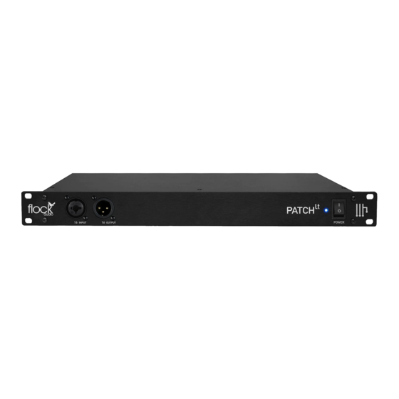
Page 7: Front Panel Identifications
FRONT PANEL FRONT PANEL INDENTIFICATIONS Front Input 16 Neutrik XLR/TRS Combo Jack (Activated using Software) Power LED Indicator Blue LED Power Indicator Power Toggle Switch Front Output 16 Toggle On/Off Master Power Switch Neutrik XLR Male Jack (Activated using Software) PATCH MANUAL FRONT PANEL IDENTIFICATIONS... -
Page 8: Rear Panel Identifications
INPUTS IMPORTANT: Always ensure that the Power OUTPUTS NOTE PATCH LT IS DESIGNED WITH A FIXED Connector is fastened tightly into the Power PROFESSIONAL LINE LEVEL OF +4 TO WORK (OUTPUT) FROM EXTERNAL (OUTPUT) FROM PATCH TO Input of the PATCH LT System Hardware. -
Page 9: Rear Panel Cable Connections
INPUTS & OUTPUTS NOTICE INPUTS NOTE INPUTS & OUTPUTS ON THE REAR PANEL OF THE PATCH LT SYSTEM ARE SEPARATELY DESIGNATED. YOU CANNOT USE AN OUTPUT AS AN INPUT OR VICE VERSA. OUTPUTS PLEASE ENSURE TO AVOID RISK OR DAMAGE TO THE PATCH... -
Page 10: Hardware Chassis Measurements
HARDWARE CHASSIS MEASUREMENTS CHASSIS DIMENSIONS 431.8 mm 227.4 mm 43.8 mm 482.0 mm FRONT VIEW 3 Kg (Weight) 482.0 mm 43.8 mm 431.8 mm REAR VIEW PATCH MANUAL CHASSIS DIMENSIONS... -
Page 11: Routing Examples (Part 1)
ROUTING EXAMPLES Hardware & Software Routing Overview Standard Microphone Routing Example The PATCH Series models are all a +4 Professional line level design. When connecting microphones directly to the PATCH Series hardware, standard audio engineering practices should be exercised such as the understanding that mixing signal levels may or may not exhibit audio level &/or electronic noise floor artifacts. -
Page 12: Routing Examples (Part 2)
ROUTING EXAMPLES Hardware & Software Routing Overview Multing Routing Example The PATCH Series models are all a +4 Professional line level design. When connecting microphones directly to the PATCH Series hardware, standard audio engineering practices should be exercised such as the understanding that mixing signal levels may or may not exhibit audio level &/or electronic noise floor artifacts. -
Page 13: Routing Examples (Part 3)
ROUTING EXAMPLES Hardware & Software Routing Overview Mixing/Mastering Routing Example Interface (Output) Interface (Output) Compressor Compressor Saturation & Saturation & Harmonics Harmonics Interface (Input) Interface (Input) PATCH MANUAL ROUTING EXAMPLES... -
Page 14: Front Inputs & Outputs
Input &/or Output 16 will no longer be actively functioning on Toggle Front Input & Output the rear side of the PATCH LT Hardware unit when the Front Input (16 & 16) rerouted from rear 16 or Output 16 is activated in the application. - Page 15 Units are connected with 8 Sends and 8 Returns. This configuration example allows a user to Send 8 analog audio signals from one PATCH LT #1 to PATCH LT #2 and return 8 PATCH LT (#1) analog audio signals to PATCH LT #1 (if required).
-
Page 16: Installing New Firmware
Step by Step Installation Process for New Firmware In order to properly install new available Firmware onto the Flock Audio PATCH LT System Hardware, you will require access to the top side of the hardware unit. Located on the top lid on the right hand facing side there are 2 small holes in the chassis lid. These holes provide access to the Bootload and Reset Buttons. -
Page 17: Troubleshooting
Navigate to the "File" tab next to the Apple logo on the top left of your screen, and select "Reset Window Size". (Mac) The PATCH LT Hardware Unit is equipped with a small cooling fan that is mounted on the right side of the Hardware Unit. This small cooling fan is There is a light humming or whirring noise coming controlled by a thermostat that will engage and disengage during the use of your System &... -
Page 18: Software & System Requirements
SOFTWARE & SYSTEM REQUIREMENTS Software Compatibility & System Requirements OSX: 10.12 Sierra or Newer Disk Space: Minimum 512 MB available disk space USB: 1x USB 2.0/3.0 Port (Per PATCH System) Required USB bandwidth: 5%-10% Memory(RAM): 4GB Minimum (8GB or more recommended) CPU: Intel Core 2 Duo (Minimum) Intel Core i3 ™... -
Page 19: User Notices & Warranty
This System or expose the internal components by opening the unit. Risk, Injury &/or Death may occur if you open a Flock Audio PATCH LT System and will warranty program comes standard with all Flock Audio PATCH LT S y s t e m p u r c h a s e s o n c e t h e h a r d w a r e i s r e g i s t e r e d a t void any active warranty immediately. - Page 20 PATENT PENDING © 2022 Flock Audio Inc. All Rights Reserved...
Need help?
Do you have a question about the PATCH LT and is the answer not in the manual?
Questions and answers