Table of Contents
Advertisement
Quick Links
Advertisement
Table of Contents

Subscribe to Our Youtube Channel
Related Manuals for Flock Audio PATCH XT


Summary of Contents for Flock Audio PATCH XT
- Page 1 USER MANUAL V.1.3.1 JANUARY 11, 2023...
-
Page 2: Table Of Contents
TABLE OF CONTENTS Thank you from Flock Audio………………………………………………..……………..3 Introduction to the PATCH XT System..……………………..………………..………….4 Important Safety Notices…………….………………………..………………..………….5 What's in the Box...…….………………………..……………..………………..………….6 Front Panel Identifications……..……………..……………………..……………….…….7 Rear Panel Identifications……….……………..…………..………..……………….…….8 Rear Panel Cable Connections………………………………..………………..………….9 Hardware Chassis Measurements……………………………..………………..………..10 The PATCH APP Overview..................11 Hardware Setup Menu....................12 Active Routings Section....................13... -
Page 3: Thank You From Flock Audio
After 2 years of strenuous work and constant focus, Flock Audio the company I started, created the worlds first and most advanced digitally controlled analog audio routing system with features never before possible in conventional analog audio routing. -
Page 4: Introduction To The Patch Xt System
INTRODUCTION INTRODUCTION TO THE PATCH SYSTEM… The Flock Audio PATCH XT System is a digitally controlled, 100% analog audio patch bay routing system. A combination of Software known as the PATCH APP and a 192 Point Connection PATCH XT Hardware component allows users to easily route and control analog audio routings without having to resort to the use of manual patch cables. -
Page 5: Important Safety Notices
Although no damage or immediate danger will occur if 48V Phantom Power #2. Avoid Liquid &/or Spills is engaged on a preamp connected to the Input of the PATCH XT System, it is not recommended to leave that 48V source active for a lengthly period of To avoid risk of damage to your PATCH XT System, avoid having liquids &/... -
Page 6: What's In The Box
WHAT'S IN THE BOX WHAT'S INCLUDED IN THE BOX PATCH XT 3U HARDWARE HARDWARE INDEX IEC POWER CABLE USB-A TO USB-B (6FT LOCKING) 6 STEP QUICKSTART GUIDE SETUP SHEETS (110V or 220V) PATCH MANUAL WHAT'S IN THE BOX... -
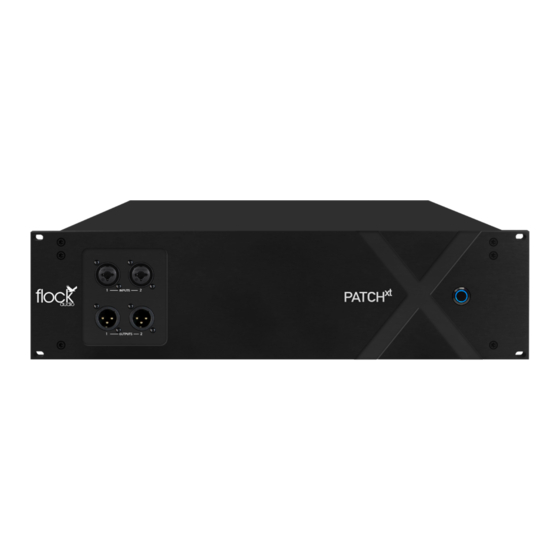
Page 7: Front Panel Identifications
FRONT PANEL Front Inputs 95-96 Multi-Purpose LED Indicator FRONT INDENTIFICATIONS Neutrik XLR/TRS Combo Jacks Blue LED Indicator (Activated using Software) (Learn more on Page 33) Front Outputs 95-96 Power Toggle Button Toggle On/Off Master Power Button Neutrik XLR Male Jacks (Activated using Software) PATCH MANUAL... -
Page 8: Rear Panel Identifications
Tascam 25 Pinout Wiring Standard INPUTS OUTPUTS PROFESSIONAL +4 LINE LEVEL NOTE PATCH XT IS DESIGNED WITH A FIXED PROFESSIONAL LINE LEVEL OF +4 TO WORK (OUTPUT) FROM EXTERNAL (OUTPUT) FROM PATCH XT TO IMPORTANT: Always ensure that the Power... -
Page 9: Rear Panel Cable Connections
INPUTS & OUTPUTS NOTICE NOTE INPUTS & OUTPUTS ON THE REAR PANEL OF THE PATCH XT SYSTEM ARE SEPARATELY DESIGNATED. YOU CANNOT USE AN OUTPUT AS AN INPUT OR VICE VERSA. PLEASE ENSURE TO AVOID RISK OR DAMAGE TO THE... -
Page 10: Hardware Chassis Measurements
HARDWARE CHASSIS MEASUREMENTS CHASSIS DIMENSIONS 425 mm 16.75 in 323.9 mm 12.75 in 133.4 mm 5.25 in 482.6 mm FRONT VIEW 19 in 25 lbs /11.3 kg (Weight) 482.6 mm 19 in 323.9 mm 12.75 in 133.4 mm 5.25 in 425 mm REAR VIEW 16.75 in... -
Page 11: The Patch App Overview
I n c l u d i n g : 4 8 V S a f e g u a rd section allows users to redirect Inputs & Outputs throughout the Active Routing Series Hardware. If Host Signal is 1-2 (Patch XT), 31-32 (PATCH) and/or 16 (PATCH Toggles, Master 48V Bypass Grid. red, the connection between the... -
Page 12: Hardware Setup Menu
HARDWARE SETUP MENU Import/Export/Save Hardware - The PATCH APP has the ability to import &/or export existing Hardware lists. When travelling to other recording studios that Hardware Setup Menu Overview use a PATCH Series System, an engineer can export the existing hardware list from the chosen studio and send it to the travelling audio engineer allowing HARDWARE SETUP MENU them to import the list and review available analog audio equipment while... -
Page 13: Active Routings Section
ACTIVE ROUTINGS SECTION Solo Paths Active Routings Section Details Users can Solo entire PATH’s by Clicking the “S” at the CUSTOMIZABLE PATH NAMES bottom of each PATH. Note: If you have Multiple PATH’s Users can customize their PATH names by right- Soloed, Un-Solo All PATH’s ACTIVE ROUTINGS SECTION by Holding Command +... -
Page 14: Understanding Signal Paths
UNDERSTANDING SIGNAL PATHS PATH Details PATH's PATH's are signal flows that go from Top to Bottom. As shown in the right hand side example, a teal arrow illustrates the analog audio signal flow as follows: Preamp Output Saturator PATH Icon Indicator Compressor Interface USED DIGITAL RACKS... -
Page 15: Understanding Path Multing
UNDERSTANDING PATH MULTING PATH Multing Details MULTING Multing capability allows a user to split an Active Routing signal flow from a desired Digital Rack Space and process the analog signal through other available analog audio equipment listed in the Hardware Index. -
Page 16: User Operation Instructions
USER OPERATION INSTRUCTIONS User Operation Instructions DRAG & DROP OPERATION In order to create an analog Routing configuration, the user will Click + Drag a preferred Digital Rack Space into the desired PATH space of their choice. Once hovering over the chosen empty rack space, the user will release the mouse button allowing the Digital Rack Space to snap into place, activating the desired Routing connection. -
Page 17: Routing Examples (Part 1)
ROUTING EXAMPLES Hardware & Software Routing Overview Standard Microphone Routing Example The PATCH Series models are all a +4 Professional line level design. When connecting microphones directly to the PATCH Series hardware, standard audio engineering practices should be exercised such as the understanding that mixing signal levels may or may not exhibit audio level &/or electronic noise floor artifacts. -
Page 18: Routing Examples (Part 2)
ROUTING EXAMPLES Hardware & Software Routing Overview Multing Routing Example The PATCH Series models are all a +4 Professional line level design. When connecting microphones directly to the PATCH Series hardware, standard audio engineering practices should be exercised such as the understanding that mixing signal levels may or may not exhibit audio level &/or electronic noise floor artifacts. -
Page 19: Routing Examples (Part 3)
ROUTING EXAMPLES Hardware & Software Routing Overview Mixing/Mastering Routing Example Interface (Output) Interface (Output) Compressor Compressor Saturation & Saturation & Harmonics Harmonics Interface (Input) Interface (Input) PATCH MANUAL ROUTING EXAMPLES... -
Page 20: Front Inputs & Outputs
Front I/O Features FRONT PANEL INPUTS & OUTPUTS The PATCH XT Hardware will allow a user to redirect Inputs and/ or Outputs 95-96 from the rear side of the system to the front panel for easy access and integration of outside analog audio equipment. -
Page 21: Multiple Unit Setup
PATCH Series hardware units. As shown in the example on the right, a PATCH unit and a PATCH XT unit are connected with 8 sends and 8 returns. This configuration example allows a user to send 8 analog audio signals from PATCH to PATCH XT and return 8 analog audio signals to PATCH (if required). -
Page 22: Front Panel Led Indicator
FRONT PANEL LED INDICATOR LED Indicator Legend - Solid Blue (Host Signal Text In PATCH APP) PATCH MANUAL LED INDICATORS... -
Page 23: Installing New Firmware
Follow the process and prompts on the firmware installer application on your computer to complete the firmware installation. Once complete, restart your PATCH XT System and the PATCH APP to complete the installation process. Note: If there are any issues installing the new firmware, please contact Flock Audio Support. -
Page 24: Troubleshooting
Confirm whether the Multi-Purpose LED is illuminated Solid Blue or Flashing. Close the PATCH APP Software and turn off the PATCH XT Hardware Unit. Wait 30 seconds and turn on the PATCH XT Hardware Unit & Reopen PATCH PATCH XT Hardware & Software not APP Software. -
Page 25: Software & System Requirements
SOFTWARE & SYSTEM REQUIREMENTS Software Compatibility & System Requirements OSX: 10.12 Sierra or Newer Disk Space: Minimum 512 MB available disk space USB: 1x USB 2.0/3.0 Port (Per PATCH Series System) Required USB bandwidth: 5%-10% Memory(RAM): 4GB Minimum (8GB or more recommended) CPU: Intel Core 2 Duo (Minimum) Intel Core i3 ™... -
Page 26: User Notices & Warranty
STANDARD LIMITED WARRANTY System or expose the internal components by opening the unit. Risk, Injury &/or Death may occur if you open a Flock Audio PATCH XT System and will All PATCH Series Systems include a 1 Year Standard Limited Warranty void any active warranty immediately. -
Page 27: End
PATENT US 11,438,719 © 2023 Flock Audio Inc. All Rights Reserved...
Need help?
Do you have a question about the PATCH XT and is the answer not in the manual?
Questions and answers