Table of Contents
Advertisement
Advertisement
Table of Contents

Related Manuals for Flock Audio PATCH

Summary of Contents for Flock Audio PATCH
- Page 1 USER MANUAL V.1.2...
-
Page 2: Table Of Contents
TABLE OF CONTENTS Thank you from Flock Audio………………………………………………..……………..3 Routing Examples (Pt.1)…………………………………………………………………..26 Introduction to the PATCH System…………………………..………………..………….4 Routing Examples (Pt.2)…………………………………………………………………..27 Important Safety Notices…………….………………………..………………..………….5 Routing Examples (Pt.3)…………………………………………………………………..28 Whats in the Box……….………………………..……………..………………..………….6 Front Panel LED Indicators………………………………………………………………..29 Front Panel Identifications……..……………..……………………..……………….…….7 Install New Firmware …………………………………………………………..………….30 Rear Panel Identifications……….……………..…………..………..……………….…….8... -
Page 3: Thank You From Flock Audio
Where do I begin to start by saying Thank you for your support… I started working on a conceptual design known as “PATCH” in early 2016 when I decided to leave my stable career and chose to pursue the path less travelled of designing and developing a better &... -
Page 4: Introduction To The Patch System
The Flock Audio PATCH System is a digitally controlled, 100% analog audio patch bay routing system. A combination of Software known as the PATCH APP and a 64 Point Connection PATCH Hardware component, combined allows users to easily route and control analog audio routings without having to resort to the use of manual patch cables. -
Page 5: Important Safety Notices
PATCH System. If accidental spill occurs, safely shut off your is engaged on a Preamp connected to the Input of the PATCH System, it is PATCH System using the front power toggle switch, unplug the wall outlet not recommended to leave that 48V source active for a lengthly period of and disconnect the 6 spin power supply from the system. -
Page 6: Whats In The Box
WHATS IN THE BOX WHATS INCLUDED IN THE BOX PATCH 1U HARDWARE PATCH APP HARDWARE INDEX IEC POWER CABLE 24VDC POWER SUPPLY USB-A TO USB-B (10FT) 6 STEP QUICKSTART GUIDE REGISTRATION KEY SETUP SHEET (110V or 220V) PATCH MANUAL... -
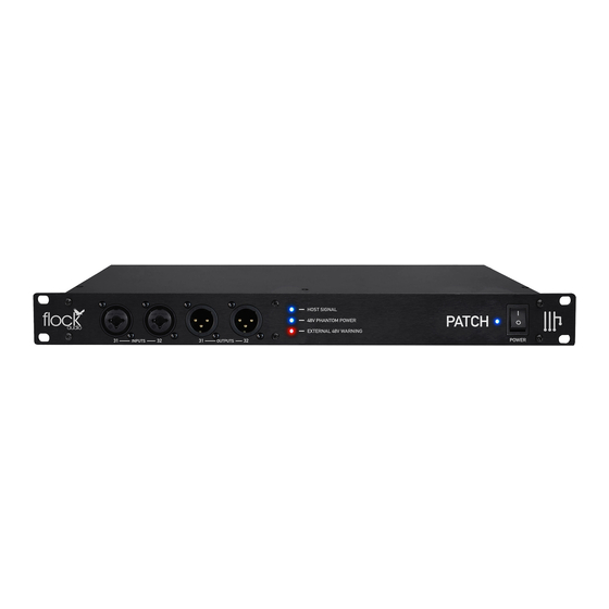
Page 7: Front Panel Identifications
Software Communication External 48V Warning LED Indicator 48V Phantom Power LED Indicator Power Toggle Switch Blue LED Indicator for Active 48V Notification Blue LED Indicator for Active 48V Notification Toggle On/Off Master Power Switch PATCH MANUAL FRONT PANEL INDENTIFICATIONS... -
Page 8: Rear Panel Identifications
IMPORTANT: Always ensure that the Power OUTPUTS Connector is fastened snuggly into the Power (OUTPUT) FROM EXTERNAL (OUTPUT) FROM PATCH TO Input of the PATCH System Hardware. GEAR TO (INPUT) OF PATCH (INPUT) OF EXTERNAL GEAR OUTPUT INPUT PATCH MANUAL... -
Page 9: Rear Panel Cable Connections
ABOUT PROPERLY CONNECTING EXTERNAL HARDWARE NOTE THAT THE DB-25 CONNECTORS ON THE REAR PANEL TO THE PATCH SYSTEM SEE THE BOTTOM OF THIS PAGE. ARE ALTERNATE ORIENTATIONS. DO NOT TRY TO FORCE THE DB-25 CONNECTOR TO CONNECT IF ITS NOT EASILY CONNECTING. -
Page 10: Hardware Chassis Measurements
HARDWARE CHASSIS MEASUREMENTS CHASSIS DIMENSIONS 431.8 mm 227.4 mm 43.8 mm 482.0 mm FRONT VIEW 4 Kg (Weight) 482.0 mm 43.8 mm 431.8 mm REAR VIEW PATCH MANUAL CHASSIS DIMENSIONS... -
Page 11: The Patch App Overview
31-32 Inputs & “Red” the connection between the Software Outputs from the rear side of the PATCH & Hardware needs to be reconnected. Hardware to the Front Panel Inputs & Outputs. OSX & WINDOWS... -
Page 12: Hardware Index & Rack Space Legend
Active Digital Rack Space Digital Rack Space Users will catalog all of their external audio equipment physically connected to the PATCH Hardware system with-in one easily organized index list. The Hardware Index allows the user to scroll Empty Rack Space through and Drag + Drop “Digital Rack Spaces”... -
Page 13: Stored Routings Menu (Pt.1)
Routings Menu Overview ROUTINGS MENU Create, Store & Recall routings from the PATCH APP’s Routing Menu. Users can create active routings and store them for later recall with this simple and easy to use user menu. The Menu is a dropdown accessible menu. -
Page 14: Stored Routings Menu (Pt.2)
OPEN ROUTINGS FOLDER By Default all routings “Saved” are stored in a community routings folder that is easily accessible with-in the PATCH APP Routings Dropdown Menu. By selecting “Open Routings Menu” it will open a dialog window, allowing the user to remove or modify any “Saved” routings. -
Page 15: Active Routings Section
Active Routings Section Details ACTIVE ROUTINGS SECTION The Active Routings Section of the PATCH APP is where users will drag + drop preferred analog audio equipment cataloged in the Hardware Index in the form of digital racks into desired PATH signal flows. -
Page 16: Understanding Signal Paths
Digital Rack Spaces that are already designated or in-use will show up “darker” or “greyed out” in the Hardware Index. This means this specific Digital rack space is already in use (i.E. Routed) in the active routings section of the PATCH APP. PATCH MANUAL UNDERSTANDING SIGNAL PATH’S... -
Page 17: Understanding Path Multing
Digital Rack Space and process the analog signal through other available analog audio equipment listed in the Hardware Index. The PATCH System does not introduce any impedance load issues to the Mult’d signal flows no matter the chosen amount of Mult’s. -
Page 18: User Operation Instructions
Space without being affected or processed. Once a Digital Rack Space is Bypassed, it will show in a darker color shade. The user will be able to UnBypass this Digital Rack by Right + Clicking again and choosing UnBypass. PATCH MANUAL USER OPERATION INSTRUCTIONS... -
Page 19: Toggle & Control Center (Pt.1)
Toggle & Control Center Features CLEAR ALL PATHS The PATCH APP Toggle & Control Center will easily allow a user to Clear (I.E. Delete) all active routing PATH’s previously set by the user. Note: When choosing “Clear All Paths” the system will... -
Page 20: Toggle & Control Center (Pt.2)
Inputs &/or Outputs 31-32 will no longer be actively Toggle Front Inputs & Outputs (31-32) rerouted from rear functioning on the rear side of the PATCH Hardware unit when the connections to Front Panel Front Inputs or Outputs 31-32 are activated in the application. -
Page 21: Hardware Setup Menu
Hardware Setup Menu Overview Export existing Hardware lists. When travelling to other recording studios that use a PATCH System, an engineer can export the existing hardware list from the chosen studio and send it to the travelling audio engineer user allowing the user to import the list and review available analog audio equipment while creating various routings before arriving at the studio. -
Page 22: Settings Menu
- To view this Manual directly from the PATCH APP above all other applications open with-in the PATCH APP a user will be able to select this option and present viewing display. open the most recent version of the User Manual. ... -
Page 23: Multiple Unit Setup Menu (Pt.1)
When using a multiple PATCH unit setup(s), users must designate specific connection configurations between PATCH units in order to send analog signals from one system to the next. PATCH Systems are identified in the PATCH APP according to their registered serial numbers. -
Page 24: Multiple Unit Setup Menu (Pt.2)
SAVE SETUP Once a desired Multiple Unit Setup configuration is established, a user must save their setup in order to properly operate their multiple system setup from the PATCH APP. UNIT COLOR ASSIGNMENT When using Multiple PATCH System units, Each PATCH System Hardware Unit is identified by a coloured outline around... -
Page 25: Multiple Unit Setup Menu (Pt.3)
PATCH Hardware Units. As shown in the right side example, 2 - PATCH Hardware Units are connected with 8 Sends and 8 Returns. This configuration example allows a user to Send 8 analog audio signals from one... -
Page 26: Routing Examples (Pt.1)
ROUTING EXAMPLES Hardware & Software Routing Overview Standard Microphone Routing Example Condenser Mic Pre-Amp Compressor Interface PATCH MANUAL ROUTING EXAMPLES... -
Page 27: Routing Examples (Pt.2)
ROUTING EXAMPLES Hardware & Software Routing Overview Multing Routing Example Condenser Mic Pre-Amp Compressor Compressor Interface Interface PATCH MANUAL ROUTING EXAMPLES... -
Page 28: Routing Examples (Pt.3)
ROUTING EXAMPLES Hardware & Software Routing Overview Mixing/Mastering Routing Example Interface (Output) Interface (Output) Compressor Compressor Saturation & Saturation & Harmonics Harmonics Interface (Input) Interface (Input) Note: Stereo Linking Feature Coming Soon. PATCH MANUAL ROUTING EXAMPLES... -
Page 29: Front Panel Led Indicators
Blue Host Signal Software Connection. - Flashing Blue (Missing Connection) - Solid Blue (Host Signal Text In PATCH APP) LED Indicator responds to notify user internal 48V is active Blue - Solid Blue (Internal 48V Active on Hardware) on the rear inputs of the PATCH Hardware. -
Page 30: Install New Firmware
Step by Step Install Process for New Firmware In order to properly install new available Firmware onto the Flock Audio PATCH System Hardware, you will require access to the top side of the hardware unit. Located on the top lid on the right hand facing side there are 2 small holes in the chassis lid. These holes provide access to the Bootload Button and Reset Buttons. -
Page 31: User Tips & Tricks
USER TIPS & TRICKS Quick User Tips & Tricks AUDITIONING MICROPHONES REARRANGE ACTIVE RACKS The PATCH System will allow you to Clicking and Dragging an Active Digital quickly audition various microphones Rack Space overtop of an already including 48V Phantom Power capable placed Digital Rack Space will initiate a microphones. -
Page 32: Troubleshooting
PATCH APP Software. If the Host Signal LED on the Hardware Unit is solid but the Host Signal Indicator in the PATCH APP is flashing, you must click Settings > Multiple Unit Setup and ensure that your PATCH Serial Number is in the first slot, then click Save Setup. -
Page 33: Software & System Requirements
Software Compatibility & System Requirements OSX: 10.7 Lion or Later (Newer) Disk Space: Minimum 512 MB available disk space USB: 1x USB 2.0/3.0 Port (Per PATCH System) Required USB bandwidth: 80%-90% Memory(RAM): 4GB Minimum (8GB or more recommended) CPU: Intel Core 2 Duo (Minimum) Intel Core i3 ™ or higher (Recommended) Internet Connection: Internet Connection is required for activation and updates. -
Page 34: User Notices & Warranty
Risk, Injury &/or warranty program comes standard with all Flock Audio PATCH System Death may occur if you open a Flock Audio PATCH System and will void any purchases once the hardware is registered at (www.flockaudio.com/ active warranty immediately. - Page 35 70208097 PATENT PENDING © 2018 Flock Audio Inc. All Rights Reserved...
Need help?
Do you have a question about the PATCH and is the answer not in the manual?
Questions and answers