
Related Manuals for Jinko JK3000-8


Summary of Contents for Jinko JK3000-8
- Page 2 Multicahnnel temperature recording (test) instrument An instruction manual Vear1.0...
- Page 3 Catalog Chapter one Safety and warranty........Introduction of instrument ......Application .......... Chapter two General overview of temperature recorder ..... Difference of temperature recorder ....Chapter three fast introduction........Introduction of product front panel....Display and function key introduction....Product rear panel introduction....... Parameters setting........
- Page 4 Preface Summary The new multi-channel temperature recorder has ultra-thin chassis, light weight, small volume and easy to carry.At the same time, the digital synchronous sampling technology has the advantages of fast measuring speed, high precision, easy to use, light and beautiful and so on. The instrument test precision is 0.5.
- Page 5 Chapter one Security Do not install on your instrument instead of parts, or execute any unauthorized modification.Please send the instrument to the maintenance department of the company to maintain it, so as to ensure its safety characteristics. Security rules In order to prevent electric shock, not authorized personnel of the company, it is strictly forbidden to disassemble the instrument and strictly prohibit the use of the equipment on the life maintenance system or any other equipment with safety requirements.We are not responsible for direct or indirect financial losses that may occur when using this product.
- Page 6 Brief introduction JK3000 is a high performance, low price temperature recorder. It can watch multi-channel temperature changes at the same time.It is very suitable for application of temperature acquisition and temperature recording.It has the RS232 interface to upload data directly to the PC, and also has the USB interface to save the measured data directly to the U disk when it is inconvenient to connect to the PC, and then transfer the data to the PC when needed.It is a half frame wide host with a top 64 channel direct slot on the back of which can be measured with a...
- Page 7 application Instrument safety index ◆Insulation resistance: the outer part of the housing and the power input are larger than 20MΩ. ◆ Withstand voltage: the power input terminal and the housing are 2 seconds withstanding voltage 1800V, and the rated current is 10mA. ◆Grounding: the power grounding pole, and the resistance between the outer shells is less than 0.2Ω。...
- Page 8 U DISK RS232 Serial Model The largest range① communication numbe number of ② channel interface JK3000-8 3 kinds of thermocouples JK3000-16 3 kinds of thermocouples JK3000-24 3 kinds of thermocouples JK3000-32 3 kinds of thermocouples JK3000-40 3 kinds of...
- Page 9 Model multichannel temperature tester Input type Thermocouple:J/K/T measuring Measuring range:-200℃~1760℃ J,K,T, range measurement accuracy: 0~1000℃:±(reading value×0.5%+1)℃,-100~ 0℃:±(reading value×0.5%+2)℃; Number of 8,16,24,32,40,48,64 channels channels Display 480*272 5 inch TFT color screen Display 1mV 0.1℃ resolution U disk storage scanning speed 100ms Internal storage Curve portrayal communication...
- Page 10 J thermocouple 0 ~ 760℃ K thermocouple 0 ~ 1370℃ T thermocouple -100 ~ 400℃ U disk: the instrument does not connect to PC. It can store data on the U disk, and save data permanently in the computer by transferring data. The 3000-8 in Table 8 is that the acquisition module with 8 channels can be used in conjunction with each of the above instruments.
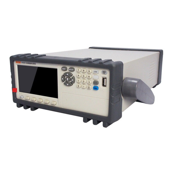
- Page 11 Chapter three Product introduction front panel Introduction of front panel 1 :display screen 2 :power 3 :System function key 4 :USB disk interface 5 :Qualified / unqualified 6 :Lock key 7 :Digital keyboard 8:Cursor key 9:show key...
- Page 12 Display area schematic: 1 :Show the temperature of each channel, respectively(001 represents first channels, 002 represents second channels), and so on. 2 :Display date / time: as shown in the picture 1th January,2007,At 20:26 00 seconds 3:Thermocouple model 4: Unit of temperature...
- Page 13 Rear panel schematic: As shown in the picture. 1:Indicating the interface definition of each channel number and input signal(01 represents 1 channels, 02 represents 2 channels, and so on.) Signal wiring method: Thermocouple Thermal resistance voltage current Signal access Signal access Signal access Signal access 2:The input voltage of the power outlet is AC220V...
- Page 14 Contact load capacity is DC 24V/1A Channel setting : 1、Select the required setup items, press the "parameter settings" key, and use the "up and down" key to set the value or function.For example, setting the number of channels: after moving the cursor to the number of channels, press the key of "parameter", change the parameters with "up and down"...
- Page 15 Temperature rise: no function at present Time setting: instrument clock Buzzer alarm: the buzzer opens or closes the choice Power saving: no function at present Upper limit alarm value: high temperature alarm value. Every 8 channels is an adjustment base, and can be switched through thermocouple type.
- Page 16 11. After all settings are finished, press "set up" to exit the parameter settings. Curve parameter page introduction: At any interface, just press the "DISP" button to return to the measurement display interface. According to the "graph" key, the curve display interface is displayed, as shown in the figure. According to the "curve setting"...
- Page 17 Font color: the color of the word on the curve page, 000~255 can be set freely. Curve color: set the color value of each channel curve, 000~255 can be set freely. Channel display: channel curve opening and closing settings, 0 passes, 1 open, every 8 channels is a set base.
-
Page 18: System Information
Press the up and down button to select the U save and click Set End . system information The system information interface includes: Instrument model Software version Hardware version Date of manufacture Instrument number... -
Page 19: Chapter Five: Instrument Communication
Chapter four install Make sure that you receive the following components when you receive multiple temperature records. If there is any shortage, please contact your dealer as soon as possible. Users choose different power JK-E171 lines according to the specifications of JK-E172 the power outlets in the area. - Page 20 USB communication requirements: we need to install USB driver software on the U disk to be used. Connect with the computer: connect the USB communication line with the instrument to the computer USB port. After the USB driver is installed, the computer will detect the USB communication interface of the instrument.
- Page 21 2. Click on the communication settings option to refresh the serial password. The baud rate of 9600 remains unchanged. 3. Click on the instrument settings option to select the thermocouple model.
- Page 22 4. Click on the choice of curve settings, select the upper and lower limits. 5. Click on the measurement display, click on the start of the test, a curve appears.
- Page 23 In the measurement display interface, click on the testing, select the Excel file in the save path and view the historical data...
- Page 24 In the File Options Interface, click View to view historical data and graphs in the save path, as well as data stored on the U disk from the instrument. Wireless mode transmission: Supporting virtual serial port, the computer must have wireless receiving function, and install virtual serial port software.
Need help?
Do you have a question about the JK3000-8 and is the answer not in the manual?
Questions and answers