Table of Contents
Advertisement
Quick Links
OPERATION MANUAL
JK9306
Digital Power Meter
Changzhou Jinailian Electronic Technology Co., Ltd
No.C3,Building 22,New Impetus Pioneering Center, No.1,Qingyang North
Road,Tianning District,Changzhou,Jiangsu,CN
TEL: 0086-519-85563477
FAX: 0086-519-85565067
https://jinailian.en.alibaba.com
www.jk17.com
www.jaldz.com
Advertisement
Table of Contents

Related Manuals for Jinko JK9306


Summary of Contents for Jinko JK9306
- Page 1 OPERATION MANUAL JK9306 Digital Power Meter Changzhou Jinailian Electronic Technology Co., Ltd No.C3,Building 22,New Impetus Pioneering Center, No.1,Qingyang North Road,Tianning District,Changzhou,Jiangsu,CN TEL: 0086-519-85563477 FAX: 0086-519-85565067 https://jinailian.en.alibaba.com www.jk17.com www.jaldz.com...
-
Page 2: Table Of Contents
Contents Chapter 1 Overview ........................1 1.1 Introduction to the instrument....................1 1.2 Unpacking Inspection........................2 1.3 Conditions of use........................2 1.3.1 Power connection........................2 1.3.2 Fuses............................2 1.3.3 Environment..........................2 1.3.4 Preheating..........................3 1.4 Instrumentation and other features...................3 Chapter 2 Front and Rear Panel Instructions and Getting Started..........3 2.1 Front panel description.......................3 2.2 Description of the rear panel......................4 Chapter 3 Basic Operation Instructions..................4... - Page 3 7.1 Basic principles........................17 7.1.1 Measurement parameters and symbols................18 7.1.2 Calculation formula......................18 7.1.3 Hardware range......................20 7.2 Instrument parameters.....................20 Chapter 8 Jinko Power Meter Module Communication Instructions V1.0......21 Chapter 9 Package and Warranty..................24 9.1 Complete Set........................24 9.2 Marks..........................24 9.3 Packaging..........................24 9.4 Transport...........................24 9.5 Storage..........................24...
-
Page 4: Chapter 1 Overview
This manual covers the JK9306 single-phase power analyzer. It covers most of the power supplies on the market with the advantages of a large input bandwidth (45 ~ 400Hz). In addition to the basic electrical parameter measurement, the four instruments also provide intuitive comparison functions. -
Page 5: Unpacking Inspection
The instrument is equipped with a fuse at the factory. Users should use the fuse provided by our company. Model difference and function description JK9306 conventional type, 600V / 2A, without harmonic analysis function 1.3.3 Environment Normal working temperature: 0 ℃ ~ 40 ℃, humidity: 20 ~ 80% RH Reference working temperature: 20 ℃... -
Page 6: Preheating
Chapter 2 Front and Rear Panel Instructions and Getting Started This chapter describes the basic operation steps of JK9306 series instruments. Before using JK9306 series instruments, please read this chapter in detail so that you can quickly familiarize yourself with the operation of JK9306 series instruments. -
Page 7: Description Of The Rear Panel
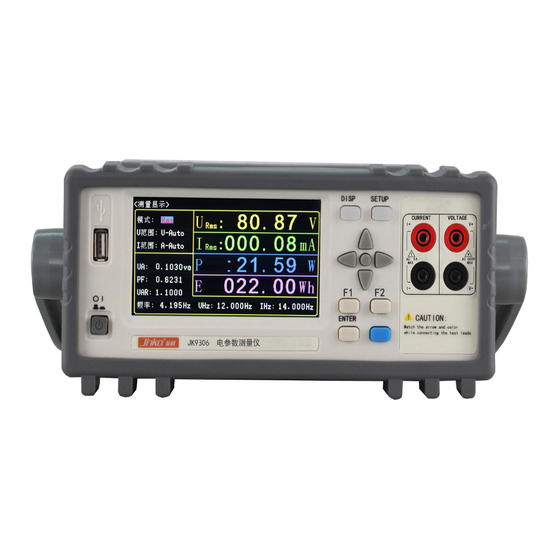
Plug in the three-wire power plug to ensure a reliable connection to the power ground. Press the power switch in the lower left corner of the front panel of the instrument to turn it on and display the startup screen. Figure 3-1 shows the startup screen of JK9306. The startup screen includes some product... -
Page 8: Switching Of The Display Interface
Tonghui Company. 3.2 Display area definition The JK9306 series uses a 24-bit color 4.3-inch color LCD screen with a resolution of 480 × 272. The content displayed on the screen is divided into the following display areas. Take the <Measurement Display A>... -
Page 9: Setup Button
Press the SETUP key to enter the system setting page. Chapter 4 Basic Page Display and Parameter Setting The general setting method of JK9306 series instruments is as follows: 1) Use the arrow keys to move the cursor to the position of the parameter to be modified;... -
Page 10: Test Mode
4.1.2 Test range JK9306 has 4 voltage test ranges: 75V, 150V, 300V, 600V, U-Auto; JK9306 has 7 current test ranges: 1mA, 3mA, 10mA, 40mA, 150mA, 500mA, 2A, I-Auto. Factory default settings: The voltage is in the automatic voltage range (U-Auto);... -
Page 11: Measurement Parameters
■ Auto / AUTO: Used to set the range to automatic mode. ■ ↓ (-): Used to select the small range down. ■ ↑ (+): Used to select a large number of ranges up. 2) Press the corresponding soft key or press ENTER to complete the corresponding setting. 4.1.3 Measurement parameters Measurement parameter settings under the measurement display page (display 5 measurement parameters),... -
Page 12: Calibration Mode Setting
5.2 Calibration mode setting: The instrument supports 4 kinds of calibration methods, which are 8n0, 8n1, 8e1, 8o1. Users can set according to their needs. The setting steps are as follows: Use the cursor keys to move the cursor to the calibration mode area, press the [ENTER] key, and then press the up and down keys to select. -
Page 13: Filter Settings
5.4 Filter settings The instrument can set the filter on and off. Users can set it according to their needs. The setting steps are as follows: Use the cursor keys to move the cursor to the filter area, press [ENTER], then press the up and down keys to select, “On”... -
Page 14: Zero Reset Setting
5.6 Zero-setting: The instrument can be set to zero setting on and off. Users can set it according to their needs. The setting steps are as follows: Use the cursor keys to move the cursor to the zero return area, press the [ENTER] key, then press the up and down keys to select, "On"... -
Page 15: Measurement Source Settings
5.8 Measurement source settings The instrument can set the measurement source settings on and off. Users can set according to their needs. The setting steps are as follows: Use the cursor keys to move the cursor to the measurement source area, press the [ENTER] key, then press the up and down keys to select, "On"... -
Page 16: Shortcut Settings
5.10 Shortcut Settings The instrument can be set with shortcut keys on and off. Users can set it according to their needs. The setting steps are as follows: Use the cursor keys to move the cursor to the shortcut key area, press the [ENTER] key, then press the up and down keys to select, "On"... -
Page 17: Power Cap
5.12 Power Cap The instrument supports setting the upper power limit. The setting range is 0000.0 ~ 9999.9W. The setting steps are as follows: Use the cursor keys to move the cursor to the power upper limit area, press the [ENTER] key, and then press the up and down keys to select. -
Page 18: Alarm Sound Setting
Chapter 6 Proper Measurement 6.1 Wiring method JK9306 series instruments provide four test wiring input terminals, namely high voltage end, low voltage end, high current end, and low current end. Because the voltage and current are floating inputs, there can be multiple combinations of test wiring methods, and different applications can be connected to the corresponding test circuit. -
Page 19: Current Terminal Internal Connection
6.1.1 Current terminal internal connection This method is suitable for low-power testing, that is, the test current is relatively small. It is recommended to use it to make the current test more accurate, and the voltage measurement will cause small errors due to the voltage drop caused by the current on the ammeter (This error can be ignored). -
Page 20: Chapter 7 Basic Principles And Technical Specifications
System principle and functional block diagram, as shown in Figure 7-1: (Figure 7-1 System Structure) The main structure of the JK9306 series single-phase power meter is to input the voltage and current of the equipment under test through the instrument to the instrument through differential input. -
Page 21: Measurement Parameters And Symbols
7.1.1 Measurement parameters and symbols U RMS: True RMS value of voltage I RMS: True RMS value of current U AC: RMS value of voltage AC component I AC: RMS value of current AC component U DC: DC component of voltage I DC: DC component of current Freq: frequency of input source PF: power factor CFu: voltage peak factor P: active power CFi: current peak factor VA: total power... - Page 22 The ratio of the absolute value of the sampling point with the largest absolute value to the effective value of the current in a sampling period /THD The calculation of voltage and current total harmonics provides two calculation standards, namely the IEC standard and the CSA standard.
-
Page 23: Hardware Range
7.1.3 Hardware range Voltage range and current range can be controlled in two ranges, modes: automatic, manual (hold, increase, decrease) There are 4 voltage ranges, as detailed in the table below: JK9306 voltage range Range number Voltage range 150V 300V... -
Page 24: Chapter 8 Jinko Power Meter Module Communication Instructions V1.0
Chapter 8 JINKO Power Meter Module Communication Instructions V1.0 I. Communication byte format: 115200 (default) 8-bit data, 1 stop bit, no parity II. Communication frame format: PC sends: 55 (h) -Addr-Command-CS Explanation: 1. The upper computer sends a total of 4 bytes, all of the above data is hexadecimal, single-byte data. - Page 25 The format of power and power factor conversion is the same, that is, the floating point number is converted into four bytes of data. Convert this four bytes to a floating point number III. Communication commands and return data 1.Common commands 10H power take command code Echo AAH + address 1 + 10H + voltage 4 + current 4 + power 4 + frequency 4 + power factor 4 + check 1 = 24byte)
- Page 26 4. Baud rate setting (power off and restart after setting) 80H Set the serial port baud rate to 115200 81H Set serial baud rate to 9600 Return: AAH + address 1+ command code + check 1 = 4Byte 5.Status code 90H Read module status information Return: AAH + address 1+ command code + code...
-
Page 27: Chapter 9 Package And Warranty
Chapter 9 Package and Warranty 9.1 Complete The instrument should have the following items when it leaves the factory: Name Quantity JK9306 instrument 1 set Three-wire power cord 1 piece Fuse 1 piece 1 piece Warranty card 1 piece Product certificate...
Need help?
Do you have a question about the JK9306 and is the answer not in the manual?
Questions and answers