
Related Manuals for Jinko JK2817N


Summary of Contents for Jinko JK2817N
-
Page 2: Lcr Meter
User’s Guide JK2817N LCR METER Changzhou Jinailian Electronic Technology Co., Ltd No.C3,Building 22,New Impetus Pioneering Center, No.1,Qingyang North Road,Tianning District,Changzhou,Jiangsu,CN TEL: 0086-519-85563477 FAX: 0086-519-85565067 https://jinailian.en.alibaba.com www.jk17.com www.jinko-tech.com... - Page 3 Catalog Chapter one open box installation. 1.1 Open box examination 1.2Power connection 1.3 fuse 1.4 environment 1.5 use test fixture 1.6 preheating 1.7 other characteristics of the instrument Chapter two Summary 2.1 Front panel specification 2.2 Rear panel specification 2.3 Display area definition 2.4 Main menu key and corresponding display page 2.4.1 Display main menu key [DISP] 2.4.2 Parameter settings main menu key [SETUP]...
- Page 4 5.2 The correct connection of the tested components 5.3Eliminating the influence of stray impedance 5.4 JK2817N test inductor fast operation example 5.5 JK2817N used for multi frequency list scanning to test capacitance fast operation 5.6 Comparator setup instance 5.6.1 Capacitor sorting 5.6.2 Load calibration operation example...
- Page 5 6.1.12 test signal level 6.1.13 output impedance 6.1.14 test signal level monitor 6.1.15 measurement shows maximum range. 6.1.16 DC bias voltage source 6.1.17 │Z│,│Y│,L,C,R,X,G,B accuracy 6.1.18 D accuracy 6.1.19 Q accuracy 6.1.20 θ accuracy 6.1.21 G accuracy 6.1.22 Rp accuracy 6.1.23 Rs accuracy 6.1.24 Accuracy factor 6.1.25 DC resistance DCR accuracy...
- Page 6 Chapter one Unbox installation This chapter describes some of the checks that must be done when you receive the instrument, and the conditions that must be understood and met before installing and using the instrument. 1.1 Open box examination Thank you for purchasing and using our products. After opening the case, you should check whether the instrument is damaged due to transportation.
-
Page 7: Chapter Two Summary
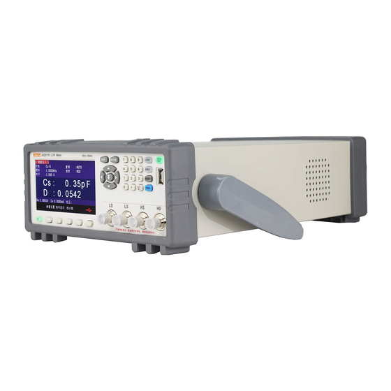
(4)Weight:about 3.6kg; Chapter two Summary This chapter describes the basic operation characteristics of JK2817N/2811B series instruments.Read this chapter carefully before using the JK2817N/2811B series of instruments so that you can quickly learn how to operate JK2817N/2811B 2.1 Front panel specification Figure 2-1 gives a brief description of the JK2817N/2811B front panel. - Page 8 Fig 2-1. Front panel specification ⑴Trademarks and modes: instrument trademarks and modes ⑵[DISP] Menu key : Press [DISP] key to enter the corresponding test display page. ⑶[SETUP] Menu key : Press the [SETUP] key to enter the test setup page and system setup interface of the instrument function(LCR Meter, transformer measurement, transformer scanning) alternately.
- Page 9 JK2832A no this function).When the measurement function is DCR, Lp-Rd and Ls-Rd, the function is invalid. ⑻PASS Indicator light,FAIL Indicator light Test qualified PASS LED Instructions,Test failed FAIL LED Instructions (9) USB HOST Interface It is used to connect U disk memory, save and invoke files, copy and save data and so on.
- Page 10 —————————————————————————————————— 2.3 display area definition JK2817N/2811B uses a 65K color 4.3 inch wide screen TFT display. The display contents are divided into the following display areas, as shown in Figure 2-3. Figure 2-3. display area definition 1) Display page area This area indicates the name of the current page.
- Page 11 < system reset > 2.5 basic operation The basic operation of JK2817N is as follows: Use menu key ([DISP], [SETUP]) and soft key to select the page you want to display. Use cursor keys ([口 ][口] [口 ] [口 ]) to move the cursor to the domain you want to set.When the cursor moves to a certain domain, the domain will be highlighted and displayed.
- Page 12 ●Signal source voltage / current monitoring(Vm,Im) ●Open circuit, short circuit, load correction ON/OFF setting status (correction) 3.1.1 Test function JK2817N can simultaneously measure two parameters of impedance element in one measurement cycle: one main parameter and one secondary parameter. The measurable parameters are as follows: Main parameter ●...
- Page 13 ● (resistance) ● (conductance) ● (DC Resistance) Secondary parameters: ● D (Loss factor) ● Q (quality factor) ● Rs (Equivalent series resistance ESR) ● Rp (equivalent parallel resistance EPR) ● Rd (DC resistance ) ● X (Reactance) ● B (electrical susceptance) ●...
- Page 14 to previous soft key menu 4)press Lp-… Soft key,The following parameters will be selected: ●Lp-Q ●Lp—Rp ●Lp—Rd ●more ●Return ●Press the corresponding soft key, select the required parameters, press the return soft key, return to previous soft key menu 5)press more ...
- Page 15 3.1.2 Test range The test range is selected according to the impedance value of the tested LCR element. JK2817N has 11 AC test ranges:1Ω, 3Ω, 10Ω, 30Ω, 100Ω, 300Ω, 1kΩ, 3kΩ, 10kΩ,30kΩ,100kΩ. Test range setting Operation steps: 1)Use cursor keys to move cursors to range fields. The screen will display the following soft keys ●...
- Page 16 15025 Test frequency setting steps: JK2817N/JK2811B have two ways to test frequency settings.One is to use soft keys, the other is to use numeric keys to input directly. 1) use cursor keys to move the cursor to the frequency domain. The screen soft key area displays the following soft keys.
- Page 17 3.1.4 Test level The test level of JK2817N /JK2811B is set according to the valid value of the sine wave signal.The frequency of the sine wave is the test frequency, and is generated by the internal oscillator of the instrument.You can set the test voltage value.can also set test current value.The...
- Page 18 Test level setting operation steps: JK2817N/JK2811B has two ways to set the test signal source level. One is the use of soft keys, the other is the use of numeric input keys. 1) Use cursor keys to move cursor to level domain. The soft key in the screen will display the following soft keys.
- Page 19 result. The soft key area of the screen will display the following soft keys. ●Decimal automatic ●Decimal lock ●Small print location plus + ●Small print location Minus- 2) Press the soft key decimal automatically to restore the position of the decimal point of the test result of the primary or secondary parameters at the corresponding cursor to the default decimal point position.
- Page 20 ●Test speed (speed) 3.2.1 Comparator function JK2817N/JK2811B built-in comparison function can divide the tested components into up to 10 BINS.(BIN1 to BIN9 and BIN OUT).can set 9 pairs of main parameter BIN limits and a pair of Auxiliary parameters BIN limits.If the main parameter of the part under test is within the BIN limit, but the Auxiliary parameters is not within the BIN limit,The tested parts are sorted into the auxiliary BIN.When JK2817N/JK2811B installs the HANDLER interface attachment, the...
-
Page 21: Auxiliary(Aux)
page. These surveillance domains can be set on the <Limit List Settings >page. ●Test parameters (parameters) ●Nominal value (nominal) ●BIN Limit value (upper / lower limit). 3.2.1 parameter The parameter area monitors the "function" parameters currently measured by the user.If the user chooses the primary and secondary parameter pair comparison mode, its parameters will be displayed as the current "function"... - Page 22 ● Test function(Function) ● Test frequency (frequency) ● Test level (level) ● Test range (range) ● Test speed (speed) 3.3.1 Trigger mode JK2817N has the following 4 trigger modes: INT (internal trigger), MAN (manual trigger), EXT 20/55...
- Page 23 When the trigger mode is set to BUS mode, the IEEE488 interface receives the "TRIGGER" command once every time,JK2817N performs a test.BUS trigger mode can not be set in the front panel of the instrument.
- Page 24 JK2817N/JK2811B can set the DC resistance range separately. The specific range is the same as that of LCR. See 3.1.2 for the specific range and operation method. 3.3.6 DC level The DC level of JK2817N and JK2831 is fixed to 0.1V , 0.3V,1V.JK2832 DC level range is 50mV-2V, resolution 0.5mV.
- Page 25 Perform the following steps to set the DC level value. Move cursor to DC level domain. 1)Use the numeric key to input the level. After pressing a numeric key, the screen soft key area displays the following unit soft key. ●...
- Page 26 When the reference element is connected to the tested end, press the soft key to measure.JK2817N/JK2811B tests the reference components, and the test results are automatically entered as reference A values. 2)Use soft keys to measure or use numeric keys to enter reference values of main parameters.
- Page 27 JK2817N /JK2811B adopts the following two open circuit correction data. JK2817N performs open-circuit calibration tests on 34 fixed frequencies in the range of 50Hz to 100kHz, regardless of your current set frequency.Mobile cursor to open area, use soft key open circuit full frequency cleared to perform full frequency open zero.
- Page 28 DC resistance function . 5)Press the soft key ON to make the open circuit correction effective.JK2817N will conduct open circuit correction in the subsequent testing process.If the frequency 1 and the frequency 2 are set to OFF, the open-circuit correction calculation uses the open-circuit correction data of the current frequency calculated by the insertion method.If frequency 1 and frequency 2 are set to ON and the...
- Page 29 Fig. 3-2 parasitic impedance JK2817N adopts the following two short-circuit correction data. No matter how many frequencies you currently set, JK2817N performs a short circuit correction test on 34 fixed frequencies in the range of 50Hz to 100kHz.Moving the cursor to the short-circuit region, the soft key short-circuit full-frequency zero-clearing is used to perform full-frequency short-circuit zero-clearing.
- Page 30 The soft key can stop the current short-circuit correction test operation, and keep the original short circuit correction data unchanged. 4)press to the short DCR of the soft key, JK2817N will measure the short circuit resistance of the DC resistance function.
- Page 31 ●Comparative function ON/OFF (comparison) ●Limit values for each BIN (LOW) ●Limit values on each BIN (HIGH) 3.5.1 exchange parameter The function of exchange parameter can exchange the main parameters and the auxiliary parameters in the parameter setting field.For example, when the test parameter is: Cp-D, the parameter interchange function changes the test parameter to: D-Cp.At this point, D can set 9 pairs of comparative limits, while Cp can set 1 pairs of comparative limits.
- Page 32 3.5.4 Comparator function ON/OFF JK2817N can set the BIN limit of 9 main parameters and the BIN limit value of a pair of parameters.The test results can be sorted into up to 10 BIN (BIN1 to BIN9 and BIN OUT).If the principal parameters of the measured part are within the limits of BIN1 to BIN9, but the auxiliary parameters are not within the limits, then the measured part is sorted into the accessory BIN.The...
- Page 33 3.5.6 Upper and lower limits JK2817N can set the bin limit of 9 main parameters and the bin limit value of a auxiliary parameters.The test results can be sorted into up to 10 BINS (BIN1 to BIN9 and BIN OUT).The upper and lower limits of these master parameters can be set in the upper and lower limit setting ranges from BIN1 to BIN9.The upper and lower limits of the auxiliary parameters can be set in the...
- Page 34 main parameter and the limit mode of the main parameter. 2)Move the cursor to the lower limit setting area of BIN 1. If you choose the tolerance mode to execute steps 3 to 6, if you choose the continuous mode to execute steps 7 to 11. 3) Use the numeric key to enter the lower limit of BIN1 in the lower limit setting field of BIN1.
- Page 35 4.1.5 Menu disping The soft key area of JK2817N products can be set to HOLD, or fixed time.When it is HOLD, the soft-key menu is always displayed, and when it is set to a certain time, the soft-key menu is...
- Page 36 automatically hidden when it is kept to the set time. When any key in the operation panel triggers the soft-key menu display, and then re-timing. Menu keep settings operation steps: 2)Move the cursor to the menu hold area. The soft key area of the screen displays the following soft keys.
- Page 37 soft key area. l)Press “OFF” ,Turn off frequency 1 point frequency clearing function. m) Move the cursor to the frequency 2 area.“ON”,“OFF”,”Open circuit single frequency clearing”,"Short circuit single frequency clearing "and" load correction"will be displayed in the soft key area. n)Press “OFF”...
- Page 38 low-end Lp) and shielding terminal corresponding to each test terminal.The purpose of shielding ends is to reduce the influence of stray capacitance on the ground and reduce electromagnetic interference.Hc, Hp, Lc and Lp should be connected on the lead of the component under test to form a complete four-terminal measurement to reduce the influence of the lead and connection point on the test results (especially loss measurement).Especially when the low impedance component is tested, the voltage sampling terminal Hp and Lp should be connected to the lead end...
- Page 39 Fig. 5-1 schematic diagram of the influence of stray capacitance Fig. 5-2 schematic diagram of eliminating the influence of stray capacitance The effect of stray capacitance can not be ignored when the measured part is of high impedance (such as small capacitance). Fig. 5-1 shows an example of measuring the measured part with four terminals.In the picture, Cd is parallel to Cx, when the conductor plate is under the tested part.The capacitor Ch is connected with Cl in series and is parallel to Cx.This will result in errors in the measurement results.Placing a grounding conductor between the high and low ends of the test, Cd...
- Page 40 2.Basic parameter setting. a) Press menu key [DISP], JK2817N display < component measurement display > page. b) Use the encoder knob to move the cursor to the functional area.The current area is displayed as Cp-D, at this time Cp-…口 , Cs-…口 , Lp-…口 , Ls-…口 , more will display on the right side of the screen.
- Page 41 Press menu key [DISP], JK2817N is displayed to < component measurement display > page.The instrument will be tested continuously and the test results will be displayed in the center of the page. 7.If the test results are obviously wrong, please: a)check whether the inductance is reliably connected with the test fixture.
-
Page 42: Alarm Setting
g) Key [1],1 displays the cursor area on the screen, and the soft key area displays the available units (Hz, kHz, and MHz). Keyboard kHz. This area is changed to 1.0000k. h) Key [ ], Move the cursor to the LMT area of Scanning Point 1, which is currently displayed as - - at this point “limit data A,”... - Page 43 6.Insert the measured capacitance onto the test fixture. 7.Perform measurement operations Press[DISP] , Then press the key list to scan, so that JK2817N can be displayed to < list scan display > page.The instrument continuously scans the test and displays the test and comparison results on the page, and gives an alarm when the comparison results are H (up) or L (down).
- Page 44 Main parameter(FUN1) Auxiliary parameters(FUN2) Frequency (FRQ) 100kHz Level (LEV) Speed (SPEED) SLOW(SLOW) Auxiliary BIN switch(AUX) Main parameter tolerance mode(MODE) %TOL(Percentage tolerance method) Nominal value(NOMINAL) 270pF BIN1 LOW (BIN1 LOW) -4.6% (BIN1 HIGH (BIN1 HIGH) 4.8% BIN2 LOW (BIN2 LOW) BIN2 HIGH(BIN2 HIGH) Auxiliary parameters LOW (2nd LOW) 0.0000 auxiliary parameters LOW(2nd LOW)
- Page 45 Frequency: 100kHz Cp standard value: 11nF D standard value:0.0005 a) press key [SETUP] , Measurement settings, user correction, limit settings, list settings, file management and tools are displayed in the soft key area. b) press key”user correction”.The instrument will be displayed as < user correction > page. c) Move the cursor to the open circuit.“ON”,”OFF”and “ON””Open circuit full frequency clearing”...
-
Page 46: Chapter Six Performance And Testing
p) Move the cursor to Frequency 1. ON, OFF, open circuit single-frequency zero-clearing, short-circuit single-frequency zero-clearing and load correction will be displayed in the soft-key area. q)Keep the test fixture open circuit,Keep the hand or other source of interference away from the test fixture. - Page 47 Medium speed and fast speed will decrease when the frequency is less than 10kHz. 6.1.8 Average 1 to 255 programmable. 6.1.9 Display digits 6 digits, maximum display number 999999 Test signal 6.1.10 Test signal frequency The test signal is sine wave.Frequency accuracy:0.01% Test frequency range: 50Hz~100kHz(JK2817N) 20Hz~100kHz(JK2831) 20Hz~200kHz(JK2832) Minimum resolution:0.01Hz 45/55...
- Page 48 6.1.11 Signal mode Normal: Set the test voltage on the measurement display page, and the voltage at the measurement end may be smaller than the set voltage according to the impedance of the measured part. Constant level: automatic adjustment of internal level makes the voltage on the tested part consistent with the set voltage.
- Page 49 0mA—±50mA, Minimum resolution:5μA 30ΩInternal resistance: 0V— ±3V Minimum resolution:0.5mV, Accuracy:1%x Set voltage+5mV 0mA—±100mA, Minimum resolution:5μA Accuracy of measurement Measurement accuracy includes measurement stability, temperature coefficient, linearity, repeatability and calibration interpolation error. Examination of the accuracy of the instrument must be carried out under the following conditions: a.Warm-up time: more than 30 minutes.
- Page 50 1+Qx The accuracy of G can only be used when measuring combinations in G-B. 6.1.18 D accuracy D accuracy De is given by the following De =±100 The upper form is used only when Dx is ≤ 0.1. When Dx>0.1, De should be multiplied by (1+Dx). 6.1.19 Q accuracy Q accuracy is given by the following Qe =±...
- Page 51 Dx is the value of D measured[F]. De is the accuracy of D. 6.1.23 Rs Accuracy When Dx (measured D value) ≤ 0.1 Rs accuracy is given by the following: Rse = Xx*De [Ω] Xx = 2πfLx=1divided by 2πfCx Here, Xx is the value of the measured X. [S].
- Page 52 0.1 ----when 0.4Vrms≤Vs≤1.2Vrms , The measurement speed is medium speed, slow speed and fast A value. 0.1 ---- when 0.4Vrms≤Vs≤1.2Vrms ,The measured speed is A value. when Vs<0.4Vrms or Vs>1.2VrmsA value calculation method is: according to the current measurement speed selection A, according to the current test signal voltage selection accuracy correction coefficient A (see figure B) A multiplied by Ar to get the current basic measurement accuracy A.
- Page 53 ) (1+Vs ) *(2*10) (1+Vs) 100kHz<fm≤200kHz (2.5*10 ) (2+400) l (6*10 )(1+100) fm:Test frequency[Hz] Impedance of measured parts[Ω] Test signal voltage[mVrms] When the impedance is less than 500Ω,, the use of Ka and Kb is invalid. When impedance is greater than 500Ω, the use of Kb and Ka is invalid. Table B calibration interpolation factor Kc Test frequency Direct calibration frequency...
- Page 54 Medium speed, slow speed,A=0.1 Fast speed, A=0.25 Rx is the measured resistance. 6.1.26 Leakage inductance Lk accuracy Inductance L accuracy+0.2% 6.2safety requirements The measuring instrument is type I safety instrument. 6.2.1 insulation resistance Under the reference working condition, the insulation resistance between the power terminal and the housing should not be less than50MΩ.
- Page 55 The ground terminal of the frequency meter is connected with the grounding end of the instrument.The terminal of the frequency meter is connected with the HCUR end of the capacitance tester.Changing frequency:20Hz,100Hz,1kHz,10kHz,100kHz(JK2817N 100kHz).The readings of the frequency meter should meet the requirements of the frequency of the test signal in this chapter. 53/55...
- Page 56 6.4.6 Accuracy of measurement The measuring instrument has many measuring parameters, and the basic measuring parameters are R,L,C,D,The rest of the parameters can be measured everywhere from the above parameters, so the accuracy measurement mainly on R, L, C, D measurement. 6.4.7 Capacitance C, loss D accuracy Function Cp-D...
- Page 57 Range AUTO Bias Speed Slow Short circuit and open circuit should be cleared before testing. Access to AC standard resistor 10Ω,100Ω,1kΩ,10kΩ,100kΩ,Changing the frequency,The error between the instrument reading and the standard value shall be within the allowable error range specified in this chapter with respect to the accuracy of | Z |.
Need help?
Do you have a question about the JK2817N and is the answer not in the manual?
Questions and answers