Table of Contents
Advertisement
Quick Links
Advertisement
Table of Contents

Subscribe to Our Youtube Channel
Related Manuals for NI cRIO-9036


Summary of Contents for NI cRIO-9036
- Page 1 Getting Started 2022-07-06...
-
Page 2: Table Of Contents
Connecting the cRIO-9036 to Ground........ -
Page 3: Overview
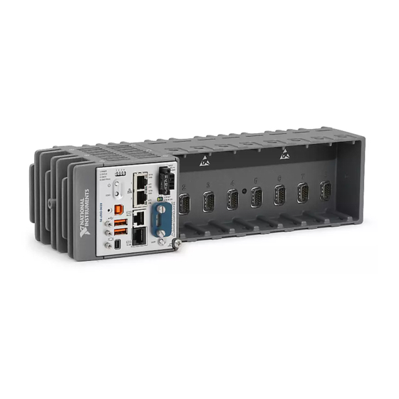
Overview This document describes how to begin using the National Instruments cRIO-9036. In this document, the NI cRIO-9036 and NI cRIO-9036 Sync are inclusively referred to as the cRIO-9036. For more information about timing and synchronization capabilities of NI cRIO-9036 Sync, visit ni.com/info... - Page 4 Safety Guidelines for Hazardous Locations The cRIO-9036 is suitable for use in Class I, Division 2, Groups A, B, C, D, T4 hazardous locations; Class I, Zone 2, AEx nA IIC T4 Gc and Ex nA IIC T4 Gc hazardous locations;...
-
Page 5: Electromagnetic Compatibility Guidelines
Special Conditions for Hazardous Locations Use in Europe and Internationally The cRIO-9036 has been evaluated as Ex nA IIC T4 Gc equipment under DEMKO 12ATEX 1202658X and is IECEx UL 14.0089X certified. Each device is marked II 3G and is suitable for use in Zone 2 hazardous locations, in ambient temperatures of -40 °C ≤... - Page 6 The DC power input cables may be unshielded. Caution To ensure the specified EMC performance, you must use an isolated cable with the RS-485 serial port, such as NI part number 184428-01. Caution To ensure the specified EMC performance, the length of any cable connected to the video and V2 ports must be no longer than 3 m (10 ft).
-
Page 7: Preparing The Environment
EMC performance is attained. Preparing the Environment Ensure that the environment in which you are using the cRIO-9036 meets the following specifications. Operating temperature (IEC 60068-2-1, IEC 60068-2-2) -40 °C to 70 °C... -
Page 8: Verifying The Kit Contents
Verify that the following items are included in the cRIO-9036 kit. Installing Software on the Host Computer Before using the cRIO-9036, you must install the following application software and device drivers on the host computer in this order: Sequence cRIO-9036... -
Page 9: Installing C Series Modules
Verify that power is not connected to the I/O connector(s) on the C Series module before you remove a module from the cRIO-9036. If the system is in a nonhazardous location, the cRIO-9036 can be powered on when you remove modules. -
Page 10: Connecting The Crio-9036 To Ground
Complete the following steps to ground the cRIO-9036. 1. Attach the ring lug to the wire. 2. Remove the grounding screw from the grounding terminal on the cRIO-9036. 3. Attach the ring lug to the grounding terminal. 4. Tighten the grounding screw to 0.5 N · m (4.4 lb · in.) of torque. -
Page 11: Connecting The Crio-9036 To Power
NI recommends the power supplies listed in the following table for the cRIO-9036. Power Supply Part Number NI PS-15 Industrial Power Supply (24 V DC, 5 A, 100 V AC to 120 V AC/200 V AC to 781093-01 240 V AC input) - Page 12 Getting Started What to Do Complete the following steps to connect a power supply to the cRIO-9036. 1. Ensure that your power supply is powered off. 2. Install the ferrite on the negative and positive leads of the power supply, as shown in the following figure.
-
Page 13: Connecting The Crio-9036 To The Host Computer
8. Power on the primary power supply and optional secondary power supply. Powering On the cRIO-9036 When you power on the cRIO-9036 for the first time, the device boots into safe mode. The POWER LED illuminates, the STATUS LED illuminates briefly, and then the STATUS LED blinks twice every few seconds. -
Page 14: Configuring The System In Measurement & Automation Explorer (Max)
Complete the following steps to set a system password. Note The default username for the cRIO-9036 is admin. There is no default password for the cRIO-9036, so you must leave the password field blank when logging in until you set a system password. -
Page 15: Installing Software On The Crio-9036
6. Select NI Scan Engine from the software add-ons. Select any additional software to install. If you plan on using the cRIO-9036 with the LabVIEW FPGA Module, you can click Next. Click NI Scan Engine if you plan on using the cRIO-9036 without the LabVIEW FPGA Module. -
Page 16: Troubleshooting The Crio-9036
■ steps. 1. Use a USB A-to-B cable to connect the cRIO-9036 USB device port to a host computer. The USB driver creates a virtual network interface card and assigns an IP address to the cRIO-9036 in the format of 172.22.11.x. - Page 17 3. Set a new DHCP connection by holding the RESET button down for 5 seconds. The STATUS LED repeats the same behavior from Step If the cRIO-9036 fails to set a new DHCP address, it assigns itself a link-local IP address. If the DHCP connection is successful and appropriate for your application, skip to Step 4.
-
Page 18: System Reset
If you are using an intelligent switch on the network, ensure that it is not disabling UDP port 44525. System Reset The following figure shows the reset behavior of the cRIO-9036. Figure 3. Reset Button Behavior Press and hold RESET button for <... -
Page 19: Ni Crio-9036 Sync Firmware Licensing
Indication Color Yellow Blinks twice and The cRIO-9036 is in safe mode. Software is not installed, which is the pauses factory default state, or software has been improperly installed on the cRIO-9036. An error can occur when an attempt to upgrade the software is interrupted. - Page 20 Getting Started For a copy of the software licenses applicable to the firmware for this hardware product, as well as copies of third party licenses and any required notices shipped with the firmware, visit ni.com/info and enter the Info Code .
Need help?
Do you have a question about the cRIO-9036 and is the answer not in the manual?
Questions and answers