Table of Contents
Advertisement
Quick Links
Advertisement
Table of Contents

Subscribe to Our Youtube Channel
Related Manuals for BRUEL & KJAER 4825


Summary of Contents for BRUEL & KJAER 4825
- Page 1 Documentation Modal Exciter Types 4825 & 4826 English BE 1667 – 11...
- Page 2 Modal Exciters Types 4825 & 4826 BE 1667 - 11 March 2002...
- Page 3 Safety Considerations This apparatus has been designed and tested in accordance with IEC 61010 – 1 and EN 61010 – 1 Safety Requirements for Electrical Equipment for Measurement, Con- trol and Laborator y Use. This manual contains information and warnings which must be followed to ensure safe operation and to retain the apparatus in safe condi- tion.
-
Page 4: Table Of Contents
CHAPTER 2 Operation ......................3 Preliminary ..........................3 System Checks and Connections ....................3 Mounting and Use of Modal Exciter Types 4825 and 4826 ............. 7 Practical Measurement Considerations .................. 11 CHAPTER 3 Operating Characteristics ................... 13 Performance Limits ........................13 Dimensions .......................... -
Page 6: Introduction
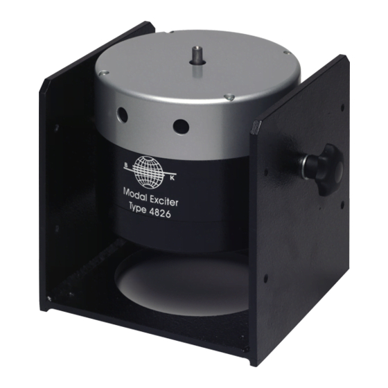
Based on unique rare-earth neodymium magnet technology, Modal Exciters Types 4825 and 4826 feature extremely small physical dimensions relative to the 200 N and 400 N force ratings along with low total weight and a low mass, high-rigidity, spring- suspended armature. - Page 7 This blower is a heavy-duty – yet compact and quiet – industrial grade blower en- suring superior reliability and durability. An air switch is built into Types 4825 and 4826 for protection of the modal exciter when used without forced cooling. During operation without forced cooling, the air switch will automatically be set in a position that limits the current to the exciter by half, effectively protecting the modal exciter against over-current.
-
Page 8: Operation
Chapter 2 Operation Preliminary Environment Modal Exciters Types 4825 and 4826 are designed for operation at ambient tempera- tures between 5° and 40°C (41° an 104°F). System Checks and Connections Before operation, the following system checks and connections should be carried... - Page 9 AF 1101 AN 0010 Power Amplifier 2720 200N Blower UH 1035 010250 The power socket of Type 4825 accepts a 4-pin Neutrik Speakon plug. The pin con- nections are shown in Fig.2.2. Fig.2.2 Drive Signal 4-pin Neutrik Speakon (Coil Start)
- Page 10 CHAPTER 2 Operation Fig.2.3 Brown Drive cable AQ 0649 for connection of Type 4825 and Power Amplifier Type Yellow/Green 2720. Soldering side of plug shown Blue Black 010113/2 Connection of Modal Exciter Type 4826 The typical setup for operation of Modal Exciter Type 4826 is shown in Fig.2.4.
- Page 11 In order to secure the correct method of cooling make sure that the air hose is attached to the air inlet of the blower, not the outlet. An air switch is built into Types 4825 and 4826 for the protection of the modal exciter when used without forced air cooling. During operation without forced air cooling, the air switch is automatically set in a position that limits the current to the exciter, effectively protecting the modal exciter against over-current.
-
Page 12: Mounting And Use Of Modal Exciter Types 4825 And 4826
Mounting and Use of Modal Exciters Types 4825 and 4826 Modal Exciters Types 4825 and 4826 can be used in any position and angle relative to the structure under test. Mounted in its trunnion, the exciter can be placed di- rectly on the floor. - Page 13 Modal Exciters Types 4825 & 4826 Connecting Structure, Force Transducer and Modal Exciter Setting up Modal Exciters Types 4825 and 4826 for a traditional frequency response function (FRF) based modal test, requires, apart from the modal exciter with a matching power amplifier, an input transducer and an interconnecting component, normally called a stinger.
- Page 14 Modal Exciter Stands UA 1607 and UA 1608 may prevent it from being successfully installed. Using DC Static Centering Unit Type 1056 means that Modal Exciters Types 4825 and 4826 – mounted in trunnion – can be placed at any position and angle, and a tension wire can still be used.
- Page 15 Highest force measurement accuracy is achieved by ensuring that Modal Exciters Types 4825 and 4826 are setup to be perfectly co-linear with the measurement axis of the input transducer. In this way, the interconnecting push/pull stinger will trans- fer the least possible torque to the input transducer and ensure that exciter and test object are effectively rotationally decoupled.
-
Page 16: Practical Measurement Considerations
The lighter the mass of the moving element in the exciter, the smaller this problem will be. Modal Exciters Types 4825 and 4826 have been fitted with low weight, preci- sion machined magnesium armatures that help to ensure minimial problems with force drop-offs. - Page 17 Modal Exciters Types 4825 & 4826...
-
Page 18: Operating Characteristics
Chapter 3 Operating Characteristics Performance Limits Fig.3.1 Sine performance curves for Modal Exciter Type 4825 Type 4825 1000 1000 10000 Frequency (Hz) mass = 0Kg at 88g mass = 0.4Kg at 32g mass = 1.5Kg at 16g mass = 2.5Kg at 12g... -
Page 19: Dimensions
10000 Frequency (Hz) mass = 0Kg at 100g mass = 0.4Kg at 51g mass = 1.5Kg at 27g mass = 2.5Kg at 16g 010244/1 Dimensions Fig.3.3 Dimension of Modal Exciter Types 4825 and 4826 (in millimetres) ø200 ø10 ø7 010125... - Page 20 CHAPTER 3 Operating Characteristics Moving Elements The low armature weight helps to ensure high-quality force measurements by mini- mising force drop-offs at the test specimen's resonance frequencies. Four upper and four lower radial flexures, the latter providing an additional guide for best stabilisa- tion, form a strong rectilinear guidance system that keeps the driver coil perfectly centered in the magnetic assembly’s air gap.
- Page 21 Modal Exciters Types 4825 & 4826...
-
Page 22: Specifications
Chapter 4 Specifications Table1 Exciter Type 4825 Type 4826 Matching Power Amplifier Type 2720 Type 2721 Matching Blower UH 1035 UH 1035 Rated Force – without forced air cooling [sine (peak)/ 100/70 N 100/70 N random (RMS)] Rated Force – with forced air cooling... -
Page 23: Compliance With Standards
Modal Exciters Types 4825 & 4826 Compliance with Standards CE-mark indicates compliance with: EMC Directive and Low Voltage Directive. C-Tick mark indicates compliance with the EMC requirements of Australia and New Zealand. Safety EN 61010-1 and IEC 61010-1: Safety requirements for electrical equipment for measurement, control and laboratory use. -
Page 24: Service And Repair
Chapter 5 Service and Repair Types 4825 and 4826 are designed and constructed to provide many years of safe, reliable operation. However, if the correct function or operating safety of the instru- ment is impaired, disconnect it immediately from the mains source and secure it against unintended operation. - Page 25 Modal Exciters Types 4825 & 4826...
- Page 26 HEADQUARTERS: DK-2850 Nærum · Denmark · Te lephone: +4545800500 · Fax: +4545801405 · http://www.bksv.com · e-mail: info@bksv.com Australia (02)9450-2066 · Austria 0043-1-8657400 · Brazil (011)5182-8166 · Canada (514)695-8225 · China (86) 1068029906 Czech Republic 02-67021100 · Finland (0)9-755 950 · France (01)69907100 · Germany 06103/733 5-0 · Hong Kong 25487486 · Hungary (1)2158305 Ireland (01)803 7600 ·...
Need help?
Do you have a question about the 4825 and is the answer not in the manual?
Questions and answers