Table of Contents
Advertisement
Quick Links
Advertisement
Table of Contents

Related Manuals for BRUEL & KJAER 4297


Summary of Contents for BRUEL & KJAER 4297
- Page 1 USER MANUAL Sound Intensity Calibrator Type 4297 BE 1653 – 14 English...
- Page 3 Sound Intensity Calibrator Type 4297 User Manual BE 1653 – 14 April 2017 www.bksv.com...
- Page 4 Health and Safety Considerations Electrical Hazards This apparatus has been designed and tested in accordance Warning: Any adjustment, maintenance and Safety with IEC/EN 61010 – 1 ANSI/UL 61010 – 1 repair of the open apparatus under voltage must Requirements for Electrical Equipment for Measurement, be avoided as far as possible and, if unavoidable, Control and Laboratory Use .
- Page 6 Brüel & Kjær has made every effort to ensure the accuracy of Brüel & Kjær and all other trademarks, service marks, trade the information contained in this document. No responsibility names, logos and product names are the property of is accepted for any errors or omissions herein. It is the Brüel &...
-
Page 7: Table Of Contents
Contents CHAPTER 1 Introduction and Description ....................1 Introduction ..........................1 Description..........................1 CHAPTER 2 Calibration Procedure with Hand-held Analyzer Type 2270-S Sound Intensity System....9 Sound Pressure Calibration....................... 9 Phase Calibration and Pressure-Residual Intensity Index Verification ........13 CHAPTER 3 Calibration Procedure with Type 2260-E Investigator™... -
Page 9: Introduction And Description
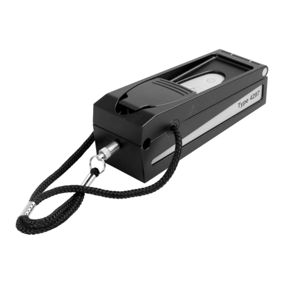
PULSE™. Type 4297 is a complete sound intensity calibrator in one compact, portable unit with a built-in sound source. A barometer is not required as the acoustic feedback system automatically adjusts for variations in atmospheric pressure. - Page 10 Sound Intensity Calibrator Type 4297 – User Manual Type 4297 is intended for use with Brüel & Kjær Sound Intensity Probes Type 3599 or 3654 (or earlier Types 3545, 3548, 3583, 3584 or 3595) with a Sound Intensity Microphone Pair Type 4197 (or earlier Type 4181).
- Page 11 Fig.1.2 shows an arrangement for measuring the pressure-residual intensity index. The probe is placed in the Type 4297. The sound source produces the same sound pressure level at each microphone, so both microphones are exposed to the same sound pressure and same phase, and therefore any intensity detected is residual intensity.
- Page 12 Sound Intensity Calibrator Type 4297 – User Manual Fig.1.2 Type 4297 Sound Intensity Calibrator with a sound intensity probe in place. This configuration is used for both sound pressure calibration and pressure-residual intensity index measurement Fig.1.3 Simplified block diagram of an intensity measuring instrument. The signals from two pressure microphones,...
- Page 13 Introduction and Description Microphones and Vent Sensitivity Type 4297 has been designed to work with Microphone Pair Types 4197 and 4181, which have an extremely low sensitivity to sound pressure at the equalisation vents due to their patented acoustical filters. When microphones are inserted into the calibrator, their diaphragms are exposed to the sound pressure in the calibrator, but their pressure-equalization vents are not.
- Page 14 Sound Intensity Calibrator Type 4297 – User Manual Fig.1.5 Typical intensity and sound pressure levels measured without spacer SPL in Coupler Intensity Level in Coupler Pressure-Residual Intensity Index 1000 10000 Frequency (Hz) 010246 1.2.2 Calibration Chart A calibration chart is supplied with each instrument in the lid of the protective case. This confirms that the specification of the calibrator is within the stated limits.
- Page 15 CHAPTER 1 Introduction and Description Fig.1.6 Type 4297 Calibration Chart 1.2.3 Use of Power Supply An external DC power supply can be used. It is not necessary to remove the internal batteries. The power supply is connected using the 5.5 mm diameter socket at the rear of the unit marked 12 V as shown in Fig.1.7.
- Page 16 Sound Intensity Calibrator Type 4297 – User Manual To replace the batteries, open the unit (see Chapter 2) and pull up the black plastic button. Lift the hinged flap to expose the battery compartment. Make sure that the new batteries are inserted with the correct polarity.
-
Page 17: Calibration Procedure With Hand-Held Analyzer Type 2270-S Sound Intensity System
Chapter 2 Calibration Procedure with Hand-held Analyzer Type 2270-S Sound Intensity System Sound Pressure Calibration 2.1.1 General To open the unit, lift the black handle into the vertical position and turn it anticlockwise through 90°, as shown in Fig.2.1. Fig.2.1 To open the unit, lift the handle and turn it 90°... - Page 18 Sound Intensity Calibrator Type 4297 – User Manual Fig.2.2 With the unit open, you can now remove the protection plug Fig.2.3 Insert the Sound Intensity Probe into the holder As shown in Fig.2.3, place the Type 3545, 3548, 3583, 3584, 3595, 3599 or 3654 sound intensity probe into the holder.
- Page 19 Fig.2.4. The unit should close without any excessive pressure being required. This indicates that the sound intensity probe is correctly fitted in the compartment. Fig.2.4 Type 4297 with a sound intensity probe in position 2.1.2...
- Page 20 Tap Ambient Pressure and enter the current barometric pressure. 6) Press the Start button on the Type 4297 control panel (see Fig.2.6). The sine wave (251.2 Hz) LED indicator should light. If it does not, the batteries need to be replaced, as described in Chapter 1.
-
Page 21: Phase Calibration And Pressure-Residual Intensity Index Verification
Please note: falsely affect readings. 9) On the Type 4297 control panel (see Fig.2.6), press the sine wave/broadband noise button again (so the broadband noise LED indicator lights) then press the Start button. 10) On Type 2270-S, tap on the... - Page 22 Sound Intensity Calibrator Type 4297 – User Manual 13) Turn off the calibrator, remove the probe, insert the protection plug and close the calibrator. ✐ The frequency range for the calibrators does not include the 8 and 10 kHz bands. Results Please note: shown from these bands are extrapolated from the 6.3 kHz band.
-
Page 23: Calibration Procedure With Type 2260-E Investigator
Chapter 3 Calibration Procedure with Type 2260-E Investigator™ Sound Pressure Calibration 3.1.1 General To open the unit, lift the black handle into the vertical position and turn it anticlockwise through 90°, as shown in Fig.3.1. Fig.3.1 To open the unit, lift the handle and turn it 90°... - Page 24 Sound Intensity Calibrator Type 4297 – User Manual Fig.3.2 With the unit open, you can now remove the protection plug Fig.3.3 Insert the Sound Intensity Probe into the holder As shown in Fig.3.3, place the Type 3545, 3548, 3583, 3584, 3595, 3599 or 3654 sound intensity probe into the holder.
- Page 25 1) With the sound intensity probe connected to your Type 2260-E Investigator , switch on Type 2260. Press the Start button on the Type 4297 control panel (see Fig.3.5). The sine wave (251.2 Hz) LED indicator should light. If it does not, the batteries need to be replaced, as described in Chapter 1.
-
Page 26: Phase Calibration And Pressure-Residual Intensity Index Verification
Sound Intensity Software BZ-7205 (BB-1131). 1) With the sound intensity probe correctly placed in Sound Intensity Calibrator Type 4297, press Start on the Type 4297 control panel (if necessary). The sine wave LED indicator will light. 2) Press the noise type toggle on the control panel to select the pink noise source. The sine wave LED indicator should now go out while the LED indictor for broadband pink noise should now light. - Page 27 4) Insert the sound intensity probe, without the microphone spacer, into Type 4297 and perform the verification exactly as described in “Verification up to 3 kHz” on page 18.
- Page 28 Sound Intensity Calibrator Type 4297 – User Manual Fig.3.7 Use the spacer to maintain the correct distance between the two microphones Fig.3.8 Sound intensity probe showing the spacer used to maintain the correct distance between the two microphones...
-
Page 29: Use Of The Calibrator With Other Instruments
PULSE LabShop 4.1.1 Sound Pressure Calibration and Pressure-Residual Intensity Index Verification PULSE LabShop does not include Type 4297 in its choice of calibrators. Before you can calibrate a sound intensity probe, a number of conditions must be met: • In the Configuration Organiser, there must be a signal for each of the two channels you are using for the sound intensity probe. -
Page 30: Using An External Signal
Please note: 1) Connect the external generator to the LEMO socket (Fig.4.1). 2) It is necessary that Type 4297 is switched on. Press Start and select broadband pink noise. The LED indicator should be illuminated. 3) Ensure that the rms voltage applied to Type 4297 does not exceed 70 mV rms (94 dB approximates to 65 mV with the spacer in place, but the exact figure is dependent on the frequency applied). -
Page 31: Pressure-Residual Intensity Index
Chapter 5 Pressure-Residual Intensity Index The information below is valid for intensity measurement systems which use probes equipped with pressure-sensing microphones and which work out the intensity in accordance with the described principle. ✐ Even under laboratory conditions, it is very difficult to create a free-field situation where Please note: the angle between the propagation of the sound wave and the probe axis is exactly 90°. - Page 32 Sound Intensity Calibrator Type 4297 – User Manual 3) In practice, if a sound wave is incident at 90°, then small differences between the phase responses of the microphones cause a small phase difference between the microphone signals. There now appears to be a flow of acoustic energy along the probe axis.
- Page 33 CHAPTER 5 Pressure-Residual Intensity Index Measured Pressure Level 1 2 ⁄ φ 20log --------------------------------------------------------------------- - Measured Intensity Level φ 10log -------------------------------- - ω ρ Δ where φ = φ + φ : phase difference between measured pressures φ : phase error of measurement system φ...
- Page 34 Sound Intensity Calibrator Type 4297 – User Manual Fig.5.3 Error due to Phase Mismatch Error due to phase mismatch for intensity measurements ) - (L -15dB 890651/2 Phase corrected intensity can be calculated by certain measurement systems in accordance with the following formulae: ------------ - –...
-
Page 35: Specifications
Chapter 6 Specifications ✐ Please note: Temperature Coefficient: < ± 0.002 dB/°C Humidity Coefficient: Negligible • All specifications are for a probe with a 12 mm Total Harmonic Distortion: <2% spacer unless otherwise stated SOUND PRESSURE LEVELS MEASURED WITH SPACER •... - Page 36 Sound Intensity Calibrator Type 4297 – User Manual COMPLIANCE WITH STANDARDS The CE marking is the manufacturer's declaration that the product meets the requirements of the applicable EU directives RCM mark indicates compliance with applicable ACMA technical standards – that is, for...
-
Page 37: Chapter 7 Service And Repair
Accredited Calibration It is recommended that you return your Sound Intensity Calibrator Type 4297 to the Brüel & Kjær Service Centre at Nærum, Denmark, for Accredited Calibration (part number 4297 CAF) every 12 months. Your local service representative can arrange this for you. - Page 38 Sound Intensity Calibrator Type 4297 – User Manual...
-
Page 39: Sensitivity To Sound Pressure At The Equalization Vent
Appendix A Sensitivity to Sound Pressure at the Equalization Vent Ideally, the pressure-sensing microphones used with an intensity probe should only detect the sound pressure at their diaphragms. In other words, the sensitivity to sound pressure at their static-pressure equalization vents should be zero. Microphone Pairs Types 4181 and 4197 are designed to have a very low vent sensitivity. -
Page 40: Measurement Errors
The low vent sensitivity leads to more accurate intensity measurements in the field. It has also made it possible to develop Sound Intensity Calibrator Types 3541 and 4297 for measurement of pressure-residual intensity index over a wide frequency range. Types 4297 and 3541 apply sound pressure to the microphone diaphragms only, and therefore, can only be used with microphone pairs such as Types 4181 and 4197. -
Page 41: Effect Of Ambient Conditions
Sensitivity to Sound Pressure at the Equalization Vent Fig.A.2 Nomogram for determining the error in a pressure-residual intensity index measurement due to vent sensitivity Measurement Systems r: 12mm [20 Hz] Measurement Systems r: 50mm [20 Hz] Freq.Hz 891394 Effect of Ambient Conditions Temperature and Atmospheric Pressure Changes To determine the sound intensity level correctly, the air (gas) density should be entered into the measurement system. - Page 42 Sound Intensity Calibrator Type 4297 – User Manual The correction to the indicated sound intensity level is: 1013 × (real) – (measured) --------------------------------------------- - × where: : ambient temperature, °C : ambient pressure, hPa For air, the deviation from the correct reading due to deviating temperatures and pressure is given in Fig.A.3.
-
Page 43: Index
Index Accessories .............. 7 Introduction .............1 Accredited Calibration ........... 29 ISO 9000 Standard ..........29 Accredited Initial Calibration ......... 29 Atmospheric Pressure Changes ......33 Low Frequencies ............32 Battery Replacement ..........7 Measured Intensity Level ........25 Measured Pressure Level ........25 Calibration ............. 15 Measurement Errors ..........32 Calibration Chart ............. - Page 44 Sound Pressure Calibration with Type 2260-E ..15 Sound Pressure Calibration with Type 2270-S ..9 Use of Power Supply ..........7 Specifications ............27 Verification Above 3 kHz ........19 Temperature and Atmospheric Pressure Changes 33 Verification Up To 3 kHz ......... 18 Type 2260-E Sound Level Meter ......
- Page 46 © Brüel & Kjær. All rights reserved. www.bksv.com...
Need help?
Do you have a question about the 4297 and is the answer not in the manual?
Questions and answers