Table of Contents
Advertisement
Quick Links
Advertisement
Table of Contents

Subscribe to Our Youtube Channel
Related Manuals for Audio Technica ATDM-0604A


Summary of Contents for Audio Technica ATDM-0604A
- Page 1 ATDM-0604 User Manual DIGITAL SMARTMIXER...
-
Page 2: Table Of Contents
Contents Introduction ..................3 Operator screen .................. 21 Checking the package contents ............3 Administrator screen ................. 22 Trademarks .................... 3 Header ......................22 Safety precautions ................4 Indicators ......................23 Important information ..................4 How to view audio input and output screens ..........24 Setting the audio input details ............ - Page 3 Contents SmartMixer ...................... 52 Audio-Technica LINK ..................55 Front panel operation restriction ..............58 Recalling Preset ....................59 About preset ....................60 Copying settings ..................... 63 Resetting settings .................... 64 Linking channels ....................65 Using the ES954 (Hanging Microphone Array) ..........66 Ducking function .....................
-
Page 4: Introduction
Introduction Thank you for purchasing this Audio-Technica product. Before using the product, read through this user manual to ensure that you will use the product correctly. Please keep this manual for future reference. Checking the package contents Before use, check to make sure that all of the following items are contained in the package. If any of the items is missing from your package or damaged, contact your local Audio-Technica dealer. -
Page 5: Safety Precautions
Safety precautions Important information Warning: To prevent fire or shock hazard, do not expose this apparatus to rain or moisture. Caution: Do not expose this apparatus to drips or splashes. To avoid electric shock, do not open the cabinet. Refer servicing to qualified personnel only. Do not expose this apparatus to excessive heat such as that generated by sunshine, fire or other heat sources. -
Page 6: Fcc Notice
Safety precautions FCC notice Warning: This device complies with Part 15 of the FCC Rules. Operation is subject to the following two conditions: (1) This device may not cause harmful interference, and (2) this device must accept any interference received, including interference that may cause undesired operation. Caution: You are cautioned that any changes or modifications not expressly approved in this manual could void your authority to operate this equipment. -
Page 7: Notes On Use
Notes on use About the product • When using the product, also read the user manuals supplied with the devices that are to be connected. • When not using the product, remove the power plug from the power outlet. • Turn the product off before connecting or disconnecting cables. •... -
Page 8: Features
Features Features of ATDM-0604 • 4 Mic inputs, 2 Mic/Line inputs, 1 unbalanced stereo input • 2 balanced outputs, 1 unbalanced stereo output • USB audio I/O (1 stereo input and 1 stereo output) • Built-in SmartMixer that allows for a selection between gain sharing and gate modes •... - Page 9 System installation Rack-mount screw x 6 Rack mount (small) (supplied with the product) (supplied with the product) Rack mount (large) (supplied with the product) 1. Attach the rack mounts to the product. 2. Install the product on the rack. • To install the product on the rack, use the screws supplied with the rack or commercially available screws.
-
Page 10: Unbalanced Connection
System installation Unbalanced connection An unbalanced connection tends to be subject to induction noise caused by the chassis potential differences. Be sure to match the chassis potentials between devices. • Match the power supply phases between devices. • Standardize the power supply systems. •... -
Page 11: System Connection Examples
System connection examples Local discussion (Preset #2) Ceiling speaker Power amplifier Tablet / Smartphone Near-end source Web Remote for operator Main speaker Power amplifier Balanced audio cable Balanced audio cable Router Ethernet cable AC power cable AC power Switching hub Remote discussion - web conference (Preset #3) Near-end source Tablet / Smartphone... -
Page 12: Remote Discussion - Video Conference (Preset #4)
System connection examples Remote discussion - video conference (Preset #4) Ceiling speaker Far-end source Power amplifier Video conference system Tablet / Smartphone Near-end source Web Remote for operator Balanced audio cable Far-end source Internet Ethernet cable AC power cable AC power Router Switching hub... -
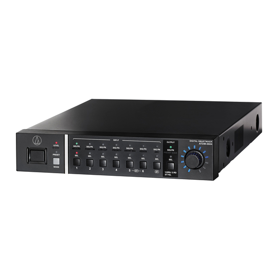
Page 13: Part Names And Function
Part names and function Front panel ❶ ❷ ❸ ❹ ❺ ❻ ❼ ❽ ❾ ❿ ⓫ ⓬ ⓭ ⓮ ⓯ ⓰ ⓱ ⓲ ❶ ❿ Power button ( SIG/PK·ASSIGN LED Turns on/off the power to the product. Indicates the signal level of input channel 6 when the level or gain ❷... -
Page 14: Rear Panel
Part names and function • An LED can be in one of five statuses. (1) Lit: Indicates that a function is selected and enabled, etc. (2) Off: Indicates that a function is not selected and disabled, etc. (3) Blinking: Indicates that a function is being selected. Repeats every 500 ms until the status changes. (4) Blinking fast: Indicates that the operation has been rejected. -
Page 15: Using The Product
Using the product Starting the product Selecting a function Press the MODE button, or turn the dial button while pressing the 1. Press the power button. MODE button, to select the function. • The PRESET LED lights, blinks, and LEVEL·GAIN LED turns on. Then, the PRESET LED turns off, and the product starts in operator mode. -
Page 16: Operations That Can Be Performed In Operator Mode/Advanced Mode
Using the product Operations that can be performed in operator Operations available only in advanced mode mode/advanced mode Change to advanced mode to perform these operations. Recalling a preset Changing the input type (MIC/LINE) Recall saved preset data to change the current setting. 1. -
Page 17: Changing The Ip Config Mode (Auto/Static)
Using the product Turning the low-cut ON/OFF Turning the AEC ON/OFF Specify whether or not to remove low frequencies from the audio signal. Turn on/off the AEC (Acoustic Echo Canceler). 1. Select "LOW CUT." 1. Select "AEC." • The SIG/PK·LOW CUT LED lights. •... -
Page 18: Locking The Front Panel
Using the product Locking the front panel A lock can be applied so that the front panel operation is disabled. 1. While pressing the OUTPUT SEL button, press and hold the dial button (for 1 or more seconds). • The front panel becomes locked. Repeat the same steps to disable the lock and enable input/output level adjustment in operator mode or gain adjustment in advanced mode. -
Page 19: Web Remote
Web Remote • If IP addresses are obtained automatically when connecting What Is Web Remote? (1) Set the product’s IP Config Mode to "Auto". – The product ships from the factory in "Auto" mode. Web Remote is a web-based application for controlling this product. With (2) Set the control device's network settings so that it connects to the Web Remote, you can remotely perform the following tasks from your network. -
Page 20: Overview Of Web Remote
Web Remote Overview of Web Remote Log in as the Operator Windows/Mac display iOS/Android display Login screen Log in as the Administrator Audio setting Input: Set the various options, such as Gain, Level, EQ, and SmartMixer, for audio input from a microphone or other audio devices. Output: Set the various options, such as Level, FBS, EQ, and Dynamics, for audio output. -
Page 21: Launch/Log Into Web Remote
Launch/Log into Web Remote Launching Web Remote Logging into Web Remote 1. Select “Operator” or “Administrator” , and then click “Login” . Launching from "Locate" • If “Administrator” is selected, the password entry field appears. Enter the password, and then click “Login” . 1. -
Page 22: Operator Screen
Operator screen If you log in as the Operator, you can import the presets, adjust the volumes, and set other options required in day-to-day operations, through simple steps. Windows/Mac screen iOS/Android screen ❹ ❶ ❶ ❹ ❺ ❷ ❻ ❸ ❺... -
Page 23: Administrator Screen
Administrator screen Header If you log in as the Administrator, you can access the input/output Settings and Settings & Maintenance screens. The header at the top remains the same on both screens. Header Input Settings Settings & Maintenance ❶ ❷ ❸... -
Page 24: Indicators
Administrator screen Indicators Status Icon display Description of each status The Audio-Technica LINK device is not connected correctly. The Audio-Technica LINK device is connected correctly. Audio-Technica LINK status There is an Audio-Technica LINK error. Remote control is disabled. Remote control is enabled. IP remote status There is a remote control error. -
Page 25: How To View Audio Input And Output Screens
Administrator screen How to view audio input and output screens ❶ ❷ ❸ ❹ ❺ ❻ ❺ ❶ ❹ Click to view the Web Remote version and the Audio-Technica You can configure the audio input settings for each input channel. ❺... -
Page 26: Setting The Audio Input Details
Setting the audio input details Changing the input type (MIC/LINE) Turning the phantom power ON/OFF Specify the input type. Turn ON/OFF the phantom power (+48V). This setting can be made only when “Mic” is selected as the input type. 1. Click the area in the red box on the screen shown below. 1. -
Page 27: Adjusting The 4-Band Eq
Setting the audio input details How to view settings screen (Expert Mode) Adjusting the 4-band EQ Set the 4-band EQ to be applied to audio inputs. ❶ ❷ 1. Click the area in the red box on the screen shown below. •... -
Page 28: Turning The Aec On/Off
Setting the audio input details Turning the AEC ON/OFF Turning the bus assignment ON/OFF Turn ON/OFF the AEC (Acoustic Echo Canceler). Switch the output bus between ON and OFF for each channel. 1. Click the area in the red box on the screen shown below. 1. -
Page 29: Setting Channel Names And Colors
Setting the audio input details Setting channel names and colors Adjusting the input level Set the name and color of each channel. Set the Mic/Line input level for each channel. 1. Click the area in the red box on the screen shown below. 2. -
Page 30: Setting The Audio Output Details
Setting the audio output details Setting the unity level Adjusting the FBS/EQ 1. Click the area in the red box on the screen shown below. 1. Click the area in the red box on the screen shown below. • The Settings screen appears. 2. - Page 31 Setting the audio output details How to view settings screen (FBS) ❶ ❷ ❸ ❹ ❺ ❻ ❶ ❷ The statuses of the bands appear. You can also switch between The frequencies of the detected feedbacks appear. ❸ dynamic and static. Select the strength to suppress the feedback.
- Page 32 Setting the audio output details How to view settings screen (EQ) ❶ ❷ ❽ ❸ ❹ ❺ ❻ ❼ ❶ ❹ Display and edit the EQ frequency characteristics waveform. The Adjust the gain of each band. ❺ pointer for each band indicates the frequency and the gain position. Adjust the frequency of each band.
-
Page 33: Turning The Dynamics Function On/Off
Setting the audio output details Turning the dynamics function ON/OFF 1. Click the area in the red box on the screen shown below. • The function is turned ON (blue)/OFF (no color) each time the switch is clicked. Adjusting the dynamics 1. - Page 34 Setting the audio output details How to view settings screen (DYN) ❶ ❷ ❸ ❹ ❺ ❻ ❼ ❽ ❾ ❿ ❶ ❺ Indicates the level of audio input to Dynamics. Set the compressor ratio. ❷ ❻ Indicates the level of audio gain suppression by the compressor. Set the compressor threshold.
-
Page 35: Turning The Delay Function On/Off
Setting the audio output details Turning the delay function ON/OFF Setting channel names and colors Specify whether or not to delay the output of each channel. Set the name and color of each channel. 1. Click the area in the red box on the screen shown below. 1. -
Page 36: Adjusting The Output Level
Setting the audio output details Adjusting the output level Setting the USB output Set the Mic/Line output level for each channel. Select the USB output bus and set the transmission level. 1. Click “USB OUT” . 1. Click the volume adjustment dial, and move it up and down to adjust the output level. -
Page 37: Setting The System Details (Settings & Maintenance)
Setting the system details (Settings & Maintenance) Advanced options for the entire system and access utilities to help Settings & Maintenance screen maintain and troubleshoot the system are available. Basic operations ❷ 1. Click the icon ( ) on the top right of the screen. ❸... -
Page 38: General In System Settings
Setting the system details (Settings & Maintenance) General in System Settings Device Name Device Name Set the name of the product being controlled from Web Remote. Header Color Set the color of the top part (header) of the Web Remote screen. After setting each item, click “Apply”... -
Page 39: Network In System Settings
Setting the system details (Settings & Maintenance) Network in System Settings IP Settings IP Control Settings Set how to obtain IP addresses, and specify each value. Set the options relating to IP control. 1. From “IP Config Mode” , select “Auto” or “Static” . 1. -
Page 40: User Access In System Settings
Setting the system details (Settings & Maintenance) User Access in System Settings Login Password Set whether or not to require a password for Administrator login. 1. Click the switch to turn on/off the setting. • The setting is turned ON (blue)/OFF (no color) each time the switch is clicked. -
Page 41: Audio In System Settings
Setting the system details (Settings & Maintenance) Audio in System Settings Audio System "Output Flip" Check/change the audio-related system settings. Output of each channel assigned to an output bus is as described below. 1. Set each item. • If “Output Flip” is turned OFF Gain Unit Type Set the unit in which the gain is displayed for adjustment. -
Page 42: Front Panel In System Settings
Setting the system details (Settings & Maintenance) Front Panel in System Settings Levels Set whether or not to enable input/output level adjustment for each channel on the front panel of the product. 1. Select/unselect the check box for each channel. •... -
Page 43: Utilities In System Settings
Setting the system details (Settings & Maintenance) Utilities in System Settings Firmware Update Reset All Settings to Default Update the firmware of the product. Reset the product to the factory defaults. (The firmware will remain the current version.) 1. Check “Serial No. ” , “Device Name” , and “Firmware Version” on 1. -
Page 44: Operator Page In Operator Access
Setting the system details (Settings & Maintenance) Operator Page in Operator Access How to view the Fader Settings screen Operator Page Restrictions ❶ ❷ ❸ ❹ Set restrictions on the operations that can be performed on the Operator page. 1. Set each item. Preset Recall Set whether or not to recall presets. -
Page 45: Presets In Presets
Setting the system details (Settings & Maintenance) Presets in Presets Presets Exporting a preset Check/change the preset settings currently registered in the product, 1. Click the radio button corresponding to the preset number from and import/export preset files. which you want to export. •... -
Page 46: Band Eq Library In Presets
Setting the system details (Settings & Maintenance) 4 Band EQ Library in Presets 4 Band EQ Library You can import/export 4-band EQ patterns to be applied to audio inputs as a preset. EQ Preset A setting in which the EQ patterns for all bands are saved. -
Page 47: Band Eq Library In Presets
Setting the system details (Settings & Maintenance) 12 Band EQ Library in Presets 12 Band EQ Library You can import/export 12-band EQ patterns to be applied to audio outputs as a preset. EQ Preset A setting in which the EQ patterns for all bands are saved. -
Page 48: Logging In Logging
Setting the system details (Settings & Maintenance) Logging in Logging Logging Set the options relating to log messages, and download log files. Enabled Set whether or not to save log messages. Destination Set whether to write log messages to the internal memory or transfer them to the Syslog server. -
Page 49: System Info In System Info
Setting the system details (Settings & Maintenance) System Info in System Info System Info System information, such as the various network settings and the product's serial number and firmware version, is displayed. -
Page 50: Key Functions
Key functions AEC (Acoustic Echo Canceler) In meetings held between remote locations, such as teleconferencing, acoustic echoes can occur when the audio output from the speaker is picked up by a microphone. The audio from the other party is amplified by the speaker and can bounce off of the ceiling, walls or floors of the room, and, upon being picked up by the microphone, is returned to the other party along with your party’s audio. - Page 51 Key functions 4. Turn AEC ON for the Mic to be used (for each channel). Setting AEC 1. Click “AEC” . 5. From “Output Bus” , select the signal (output bus) to be returned to the other party. 2. From “Mode” , select “AEC” . 6.
- Page 52 Key functions 7. Click “Start” . 10. If necessary, turn ON “NLP” . • Reverberation measurement begins. • These features may increase the echo canceling effect. • Click ”Test” to play the test audio for a check. Click it again to stop playing the test audio.
-
Page 53: Smartmixer
Key functions 2. From “Mode” , select “Gate” . SmartMixer The SmartMixer function is designed to automatically adjust the audio input and output of the microphone channel without picking up any unnecessary noise or allowing howling to occur in meetings where an unspecified large number of participants speak at the same time. - Page 54 Key functions 4. Set “Priority” , “Can Cut” , and “Off Attenuation” for each channel, Last Mic ON When this is set to ON, the last opened as necessary. microphone input channel gate remains open. Priority When this is set to ON, the gate of this Gate Hold Time Set the time after the audio input is ceased until microphone input channel opens first over the...
- Page 55 Key functions 2. From “Mode” , select “Gain Share” . 5. Assign signals to the output buses. Audio signals processed by SmartMixer are output (Purple) when SmartMixer is turned ON. ON (Blue) Assigned to an output bus. Audio signals not processed by SmartMixer are output even when SmartMixer is turned ON.
-
Page 56: Audio-Technica Link
Key functions Audio-Technica LINK Up to six ATDM-0604 model mixers can be daisy-chained so that, as a whole system, it can handle audio inputs from 24 Mic channels, 12 Mic/Line channels, and 6 unbalanced stereo channels. The proprietary Audio-Technica LINK functionality enables the transmission of low-latency, high-speed audio bus signals between devices, making it possible to steadily control and transmit uncompressed audio signals. - Page 57 Key functions 1. In “Audio-Technica LINK Mode” , set the ATDM-0604 connected to one of the two ends as “Primary” . • Do not set any of ATMD-0604 devices connected in the middle as “Primary” . The connection will not be recognized properly. 2.
- Page 58 Key functions Sharing audio buses In “Audio-Technica LINK” , the audio output buses (Output 1/L, Output 2/R, and Output ST) and the AEC reference signal bus are shared among the ATDM-0604 devices. With this, any ATDM-0604 can output audio inputs from 24 Mic channels, 12 Mic/Line channels, and 6 unbalanced stereo channels. The AEC reference signals can also be shared among the devices.
-
Page 59: Front Panel Operation Restriction
Key functions 3. Click “Front Panel” . Front panel operation restriction The following two modes are available when operating the product with the buttons and the dial on the front panel. Operator mode: In this mode, daily operations are performed, such as loading the preset settings and adjusting the audio level. -
Page 60: Recalling Preset
Key functions Administrator screen Recalling Preset 1. Click “Preset” at the top right of the screen. Operator screen 1. Click the green area at the top of the screen. 2. Select “Recall Preset” from the pull-down menu. 2. Select the preset of your choice from the pull-down menu. •... -
Page 61: About Preset
Key functions About preset The product includes preset patterns using a web or video conference. Preset #1 (Initialization of audio settings) • Reset the audio settings on the product to the factory defaults. • All settings are deleted when initialized. Accordingly, it is recommended that the settings be saved to another preset or a hard disk space. •... - Page 62 Key functions Preset #3 (Web conference) This preset is suitable for web conferencing using software codecs. The product, equipped with a USB audio interface, is capable of handling meetings held at any location using a computer or tablet with an Internet connection. It is also equipped with an echo canceler to provide quality conferencing with no echoes or dropouts.
- Page 63 Key functions Preset #4 (Video conference) This preset is suitable for video conferencing using hardware codecs. The unbalanced output on this product is compatible with both Mic and Line levels, and the output level setting can be changed according to the input level of the video conference system being used. It is also equipped with an echo canceler to provide quality conferencing with no echoes or dropouts.
-
Page 64: Copying Settings
Key functions 3. Select the a different source channel. Copying settings • To select another channel, click the channel selected. The selection of the channel is canceled. Reselect the channel to copy. The settings for a channel can be copied to another channel. 1. -
Page 65: Resetting Settings
Key functions Resetting settings The settings for a channel can be reset to the default settings. 1. Click the icon ( ) of the channel to reset. 2. Click “Reset” . -
Page 66: Linking Channels
Key functions 3. Confirm that the input channels have been linked. Linking channels • The settings of the channel 6 are same as the settings of the channel 5. • The linked channel 6 are grayed out and cannot be used. Link channels to share the settings. -
Page 67: Using The Es954 (Hanging Microphone Array)
Key functions Setting the Administrator Page Using the ES954 (Hanging Microphone Array) 1. Start Web Remote and log in as “Administrator” . Connecting and setting the ES954 1. Connect the ES954 to ATDM-0604. • Connect MIC1 to 4 of the ES954 to input channels 1 to 4 of the ATDM- 0604. - Page 68 Key functions 4. Turn on “Virtual Mic Mode” . 7. Set “Input gain” , “Low-cut” , “EQ” , “Smart Mix” , “Assign” , and “Volume” as necessary. • Input gain values on channels set as "Virtual Mic" are linked. • “Low-cut” , “EQ” , “Smart Mix” , “Bus Assignment” , and “Volume” can be set for each channel.
- Page 69 Key functions 9. Set the “Orientation” , “Pattern” , and “Tilt” of the virtual mic for 2. Click the icon ( ) at the upper right of the screen. each channel. Orientation Click the buttons around the virtual polar pattern to set the orientation of each virtual mic input channel.
- Page 70 Key functions 5. Click “Apply” . 7. You can turn the array mic and LED ring on or off by clicking “Array Mic Off” . • Setting is complete. • The on or off status of the array mic is not saved. (After restarting the power, it is on.) •...
-
Page 71: Ducking Function
Key functions 3. Click “Enabled” . Ducking function • The signal assigned to BUS1 becomes the trigger, and ducking is applied to input channel ST. The mixer has a ducking function on input channel ST. The function automatically reduces the background music volume or returns it to the original volume. -
Page 72: Menu Item
Menu Item Audio Settings Input Presets Item name Setting values Default Setting Resumed Included Input channel 1 to 6 CH # CH 1 to 6 Mode Select* Ch1 to 4: Mic, Virtual Mic Ch5, 6: Mic, Line 0dBV, Line +4dBu, ✓... - Page 73 Menu Item Presets Item name Setting values Default Setting Resumed Included 4 Band EQ Expert mode Band #1 Gain -18dB to +18dB ✓ ✓ Band #1 20Hz to 20kHz ✓ ✓ Frequency Band #1 Q 0.3 to 60 0.75 ✓ ✓...
- Page 74 Menu Item Ducking Presets Item name Setting values Default Setting Resumed Included Ducking Ducking Enable, Disable Disable ✓ ✓ Output Presets Item name Setting values Default Setting Resumed Included CH Name (Maximum 30 characters (ASCII code OUT 1, OUT 2 only)) Unity +4dBU, 0dBV, -10dBV...
- Page 75 Menu Item CH Detail Setting in Output Presets Item name Setting values Default Setting Resumed Included Band #5 Enable On, Off ✓ ✓ Band #5 Gain -18dB to +18dB ✓ ✓ Band #5 20Hz to 20kHz ✓ ✓ Frequency Band #5 Q 0.3 to 60 0.75 ✓...
-
Page 76: Settings & Maintenance
Menu Item Settings & Maintenance System Settings General Presets Item name Setting values Default Setting Resumed Included Device Name Device Name (Maximum 30 characters (ASCII code ATDM-0604 ✓ only)) Header Color White, Green, Yellow, Orange, Purple, White ✓ Cyan Audio-Technica LINK Audio-Technica LINK Primary, Extension Primary... - Page 77 Menu Item Utilities Presets Item name Setting values Default Setting Resumed Included Firmware Update Launguage Pack Install Reset All Settings to Default Operator Access Operator Page Presets Item name Setting values Default Setting Resumed Included Fader Settings Fader 1 to 8 Show On, Off ✓...
-
Page 78: Troubleshooting
Troubleshooting If you encounter a problem, please check the following. • Check whether all connections are correct. • Check whether the system is being operated according to the instructions provided in the manual. • Check whether the external devices are functioning properly. Check the devices without connecting them to the product. •... -
Page 79: Web Remote
Troubleshooting Web Remote Symptom Cause/Action Reference page You cannot “locate” the product. Check the connections of the product and the control device, such as a computer. Check whether the product and the control device, such as a computer, are connected to the same network. -
Page 80: Error Messages
Error messages Error Message Cause Action Resume Data Error Importing the resume data failed. Restart the product, and check whether the same error occurs. The product started with the previous or default settings. Preset Data Error Importing the preset data failed. Restart the product, and check whether the same error occurs. -
Page 81: Dimensions
Dimensions 326.0 13.5 44.0 217 .0 (Unit: mm) -
Page 82: Specifications
Specifications General specifications Power supply 100 to 240 V AC (50/60 Hz) Power consumption 17 W Operating temperature range 0 to 40°C (32 to 104° F) Operating humidity range 25 to 85% (with no condensation) Dimensions (excluding protrusions) 217 mm (8.54") x 44 mm (1.73") x 326 mm (12.83") (W×H×D) Weight 1.85 kg (4.1 lbs) Finish... -
Page 83: Input/Output Specifications
Specifications Other Phantom power +48 VDC PAD (Attenuation level) -24 dB I/O connector INPUT ST Euroblock connectors (3-pin) INPUT MIC/LINE 5 and 6 Euroblock connectors (3-pin) INPUT MIC 1 to 4 Euroblock connectors (3-pin) OUTPUT UNBAL Euroblock connectors (3-pin) OUTPUT BAL 1/L and 2/R Euroblock connectors (3-pin) Level indicator SIGNAL/PEAK... -
Page 84: System Diagram
System diagram Digital SmartMixer Audio data Audio data Contral data ATDM-0604 Control data Meter Meter ANALOG INPUT ANALOG OUTPUT Lv Meter Lv Meter Post Post HA Gain +20dB ~ +60dB SmartMixer IN 1 1.0dB step (Gate/Gain Sharing) Array PRS CH1 Delay Time Output unity 3 steps Channel 1... - Page 85 Audio-Technica Corporation ver.1 2017.12.01 2-46-1 Nishi-naruse, Machida, Tokyo 194-8666, Japan 222304240-02-03 ver.3 2019.02.01 ©2019 Audio-Technica Corporation...
Need help?
Do you have a question about the ATDM-0604A and is the answer not in the manual?
Questions and answers