
Related Manuals for Audio Technica ATDM-1012


Summary of Contents for Audio Technica ATDM-1012
- Page 1 User Manual ATDM-1012 DIGITAL SMARTMIXER ATDM-1012DAN DIGITAL SMARTMIXER with Dante...
-
Page 2: Checking The Package Contents
Before use, check to make sure that all of the following items are contained in the package. If any of the items is missing from your package or damaged, contact your local Audio-Technica dealer. • ATDM-1012/ATDM-1012DAN unit • Euroblock connector ×22 •... -
Page 3: Safety Precautions
Safety precautions Important information Warning: To prevent fire or shock hazard, do not expose this apparatus to rain or moisture. Caution: • Do not expose this apparatus to drips or splashes. • To avoid electric shock, do not open the cabinet. •... -
Page 4: Fcc Notice
Safety precautions FCC Notice Warning: This device complies with Part 15 of the FCC Rules. Operation is subject to the following two conditions: (1) This device may not cause harmful interference, and (2) this device must accept any interference received, including interference that may cause undesired operation. Caution: You are cautioned that any changes or modifications not expressly approved in this manual could void your authority to operate this equipment. -
Page 5: Notes On Use
Notes on use • When using the product, also read the user manuals supplied with the devices that are to be connected. • When not using the product, remove the power plug from the power outlet. • Turn the product off before connecting or disconnecting cables. •... -
Page 6: About Audio-Technica Link
About Audio-Technica LINK Up to eight ATDM-1012 model mixers can be daisy-chained so that, as a whole system, it can handle audio inputs from 80 Mic/Line channels and 16 unbalanced stereo channels. The proprietary Audio-Technica LINK functionality enables the transmission of low-latency, high-speed audio bus signals between devices, making it possible to steadily control and transmit uncompressed audio signals. -
Page 7: Unbalanced Connection
System installation Unbalanced connection An unbalanced connection tends to be subject to induction noise caused by the chassis potential differences. Be sure to match the chassis potentials between devices. • Match the power supply phases between devices. • Standardize the power supply systems. •... -
Page 8: System Connection Examples
System connection examples Power amplifier Main speaker (L) Main speaker (R) Ceiling speaker Power amplifier Near-end source Tablet / Smartphone Media recorder Remote for operator Far-end source Switching hub Media player AV switcher Internet Computer Video conference system Players such as Router Blu-ray/DVD/CD Far-end source... -
Page 9: Part Names And Function
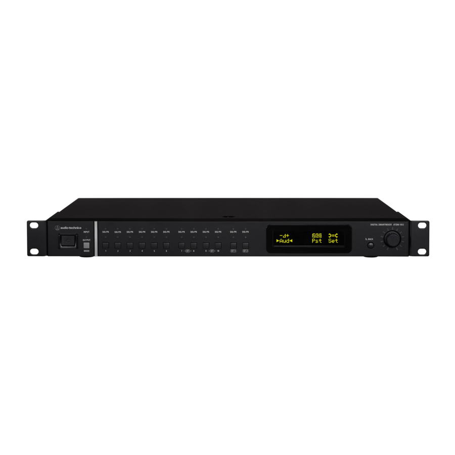
Part names and function Front Panel ❶ ❷ ❸ ❹ ❺ ❻ ❼ ❽ ❾ ❿ ⓫ ❶ Power button Turns on/off the power to the product. ❷ MODE button Switches between input/sub input/output channel modes. ❸ OUTPUT LED The LED lights in red when in output channel mode. ❹... -
Page 10: Rear Panel
Part names and function Rear panel ATDM-1012DAN ❶ ❷ ❸ ❹ ❺ ❻ ❼ ❽ ❾ ❶ Network port/Dante network port (ATDM-1012DAN) • A NETWORK port. Connect an Ethernet cable (Cat5e or above). Connect to a local area network to control externally via web remote or IP control. - Page 11 About Dante (ATDM-1012DAN only) ATDM-1012DAN supports Dante network audio. ATDM-1012DAN audio can be output to a Dante device or audio from a Dante device can be input to ATDM-1012DAN. For more details on Dante network audio, refer to the Audinate website at www.audinate.com. Network port mode settings Performing settings from the ATDM-1012DAN unit Turn the dial button on the Home screen to select “Set”...
- Page 12 About Dante (ATDM-1012DAN only) Connections in each mode Switched (Default setting) • The switching hub used for the Dante network must be gigabit-capable. Refer to the Audinate website and other information for required switching hub specifications. • Connect external controls for Dante audio and the ATDM-1012DAN to either the PRIMARY or SECONDARY port. As shown in the figure, a computer or Dante device can be connected directly to the Dante network port of ATDM-1012DAN.
- Page 13 About Dante (ATDM-1012DAN only) Split In Split mode, independent networks are necessary for both PRIMARY and SECONDARY. PRIMARY is the ATDM-1012DAN external control port and SECONDARY is the Dante audio port. Computer Tablet / Smartphone Switching hub Switching hub Dante-equipped device Dante channel list Dante send channels Dante receive channels...
-
Page 14: Starting The Product
Basic operations of the product Starting the product How to input characters Follow the procedure below to input text. Press the power button. Turn the dial to select which character to input. • The product boots in administrator mode by factory default. •... -
Page 15: Front Panel Mode
Basic operations of the product Front panel mode The following two modes are available when operating the product with the buttons and the dial on the front panel. Operator mode: In this mode, daily operations are performed, such as loading the preset settings and adjusting the audio level. - Page 16 Operations that can be performed in operator mode Adjusting the input and output levels Confirming product setting statuses Adjust the input and output levels for each I/O channel. Product setting statuses can be confirmed when in operator mode. To change settings, switch to administrator mode. Turn the dial button on the Home screen to select “Lvl”...
- Page 17 Operations that can be performed in administrator mode Matrix Assign (Matrix Assign) Audio menu (Aud) Set which input channel is sent to which bus or which bus draws from which input channel. Channel settings (Channel Setting) Turn the dial button on the Home screen to select “Aud” and Set parameters for each channel.
- Page 18 Operations that can be performed in administrator mode Setting the oscillator (Oscillator) Setting boot up presets (BootUp Presets) The product has an oscillator function on the output channels. This Sets the recalling presets when the product boots. function is convenient for checking the audio during setup or Turn the dial button on the Home screen to select “Pst”...
- Page 19 Operations that can be performed in administrator mode Setting system information (System Info) Performing logging settings (Logging) Product setting statuses can be confirmed. Perform log message settings. Turn the dial button on the Home screen to select “Set” and Turn the dial button on the Home screen to select “Set” and then press the dial button.
-
Page 20: Recommended Environment
Remote screen in the web browser. • When clicking the “Identify” button, the button will illuminate in red, and the indicator lamps on the front panel of the selected ATDM-1012 will blink. Use this function to identify a specific ATDM-1012 in the “Locate”... -
Page 21: Overview Of Web Remote
Web Remote Overview of Web Remote Log in as the Operator Windows/Mac display iOS/Android screen Login screen Log in as the Administrator Audio Settings Input: Set the various options, such as Gain, Level, EQ, and SmartMixer, for audio input from a microphone or other audio devices. Matrix: Set which input channel is sent to which bus or which bus draws from which input channel. -
Page 22: Launch/Log Into Web Remote
If you know the IP address of the product, you can launch Web Remote by specifying the IP address directly. Open the control device’s web browser. Enter the IP address of the ATDM-1012 for which you want to launch Web Remote. • Web Remote launches, and the Login screen appears. -
Page 23: Operator Screen
Operator screen If you log in as the Operator, you can import the presets, adjust the volumes, and set other options required in day-to-day operations, through simple steps. Windows/Mac display iOS/Android screen ❶ ❺ ❷ ❷ ❸ ❻ ❼ ❹ ❻... -
Page 24: Administrator Screen
Administrator screen Header If you log in as the Administrator, you can access the input/output Settings and Settings & Maintenance screens. The header at the top remains the same on both screens. Header Input Settings Settings & Maintenance ❶ ❷ ❸... -
Page 25: Error Display
Administrator screen Indicators Status Icon display Description of each status The Audio-Technica LINK device is not connected correctly. The Audio-Technica LINK device is connected correctly. Audio-Technica LINK status There is an Audio-Technica LINK error. Remote control is disabled. Remote control is enabled. IP remote status There is a remote control error. -
Page 26: How To View Audio Input And Output Screens
Administrator screen How to view audio input and output screens ❶ ❷ ❸ ❹ ❺ ❻ ❺ ❶ ❹ Click to view the Web Remote version and the Audio-Technica You can configure the audio input settings for each input channel. ❺... - Page 27 Administrator screen How to view the Matrix Assign screen ❶ ❷ ❸ ❹ ❺ ❶ Set whether Smart Mix is ON/OFF for each channel. ❷ Set whether AEC is ON/OFF for each channel. ❸ Select the NC bus. ❹ Switch the ST LINK for the bus ON/OFF. ❺...
-
Page 28: Setting The Audio Input Details
Setting the audio input details Changing the input type (MIC/LINE) Turning the phantom power ON/OFF Specify the input type. Turn ON/OFF the phantom power (+48V). This setting can be made only when “Mic” is selected as the input type. Click the area in the red box on the screen shown below. Click the area in the red box on the screen shown below. -
Page 29: Turning The Fbs On/Off
Setting the audio input details Turning the compressor ON/OFF Turning the FBS ON/OFF Switch the compressor between ON and OFF for each channel. This Switch the FBS (feedback suppressor) between ON and OFF for each setting can be made only when the compressor module is assigned. channel. -
Page 30: Adjusting The 4-Band Eq
Setting the audio input details Adjusting the 4-band EQ Set the 4-band EQ to be applied to audio inputs. Click the area in the red box on the screen shown below. • The Settings screen appears. Set each item. - Page 31 Setting the audio input details How to view settings screen (FBS) ❶ ❷ ❸ ❹ ❺ ❻ ❶ ❷ The statuses of the bands appear. You can also switch between The frequencies of the detected feedbacks appear. ❸ dynamic and static. Select the strength to suppress the feedback.
- Page 32 Setting the audio input details How to view settings screen (EQ) ❶ ❽ ❷ ❸ ❹ ❺ ❻ ❼ ❶ ❸ Display and edit the EQ frequency response waveform. The pointer In all bands, change the gain to 0 without changing the current for each band indicates the frequency and the gain position.
- Page 33 Setting the audio input details Changing settings screen The Settings screen can be in “Easy Mode” with a simplified display or in “Expert Mode” with all items displayed. Easy mode Select from the pre-arranged EQ patterns to easily adjust the Expert mode The parameters can be set for each band for finer EQ adjustment.
- Page 34 Setting the audio input details How to view settings screen (DYN) ❶ ❷ ❸ ❹ ❺ ❻ ❼ ❽ ❾ ❿ ❶ ❻ Switch between the compressor and DeEsser. Set the compressor ratio. ❷ ❼ Indicates the level of audio input to Dynamics. Set the compressor threshold.
-
Page 35: Turning The Aec On/Off
Setting the audio input details Turning the AEC ON/OFF Checking bus assignments Turn ON/OFF the AEC (Acoustic Echo Canceler). You can check which channels are assigned to which buses. Click the area in the red box on the screen shown below. •... -
Page 36: Setting Channel Names And Colors
Setting the audio input details Setting channel names and colors Adjusting the input level Set the name and color of each channel. Set the Mic/Line input level for each channel. Click the area in the red box on the screen shown below. Drag the volume adjustment dial, and move it up and down to adjust the input level. - Page 37 Setting the audio input details Setting the fader group If the channel faders for the primary and extensions are set to the same group on this screen and assigned in the “Fader Settings” (P.50) on the operator screen for the primary, the levels of channels belonging to the same group will be controlled using the fader assigned to that primary.
- Page 38 Setting the Matrix details Setting Smart Mix Setting the bus assignment Select which bus each channel will be assigned to. Select a group by clicking the area in the red box on the screen Press the button to switch between “OFF”, “ON (Smart Mix)”, and shown below.
-
Page 39: Setting The Audio Output Details
Setting the audio output details Setting channel outputs Turning the EQ ON/OFF Switch the EQ between ON and OFF for each channel. Click the area in the red box on the screen shown below. Click the area in the red box on the screen shown below. •... - Page 40 Setting the audio output details How to view settings screen (FBS) ❶ ❷ ❸ ❹ ❺ ❻ ❼ ❶ ❷ The statuses of the bands appear. You can also switch between The frequencies of the detected feedbacks appear. ❸ dynamic and static. Select the strength to suppress the feedback.
- Page 41 Setting the audio output details How to view settings screen (EQ) ❶ ❷ ❽ ❸ ❹ ❺ ❻ ❼ ❶ ❸ Display and edit the EQ frequency response waveform. The pointer In all bands, change the gain to 0 without changing the current for each band indicates the frequency and the gain position.
- Page 42 Setting the audio output details How to view settings screen (DYN) ❶ ❷ ❸ ❹ ❺ ❻ ❼ ❽ ❾ ❿ ⓫ ⓬ ⓭ ⓮ ⓯ ❶ ❺ Indicates the level of audio input to Dynamics. Set each item for the compressor. ❷...
-
Page 43: Adjusting The Dynamics
Setting the audio output details Click the area in the red box on the screen shown below. Turning the compressor ON/OFF • The setting is turned ON (blue)/OFF (no color) each time the switch is clicked. Switch the compressor between ON and OFF for each channel. This setting can be made only when the compressor module is assigned. -
Page 44: Adjusting The Output Level
Setting the audio output details Setting channel names and colors Adjusting the output level Set the name and color of each channel. Set the Mic/Line output level for each channel. Click the area in the red box on the screen shown below. Click the volume adjustment dial, and move it up and down to adjust the output level. - Page 45 Setting the audio output details Setting the fader group If the channel faders for the primary and extensions are set to the same group on this screen and assigned in the “Fader Settings” (P.50) on the operator screen for the primary, the levels of channels belonging to the same group will be controlled using the fader assigned to that primary.
-
Page 46: Setting The Usb Output
Setting the audio output details Setting the USB output Setting the oscillator Select the USB output bus and set the transmission level. The product has an oscillator function on the output channels. This function is convenient for checking the audio during setup or maintenance. Click “USB OUT”. -
Page 47: Setting The System Details (Settings & Maintenance)
Setting the system details (Settings & Maintenance) Advanced options for the entire system and access utilities to help Settings & Maintenance screen maintain and troubleshoot the system are available. Basic operations ❷ ❸ Click the icon ( ) on the top right of the screen. ❶... -
Page 48: Network In System Settings
Setting the system details (Settings & Maintenance) Click “Apply”. Network in System Settings • Setting is complete. NTP Settings Network Configuration (ATDM-1012DAN only) Set the NTP (Network Time Protocol). Set each item. Set each item. Mode Set the network configuration mode to suit the environment. Enabled Set whether to enable or disable the NTP Latency... -
Page 49: Audio In System Settings
Setting the system details (Settings & Maintenance) Audio in System Settings Utilities in System Settings Audio System Firmware Update Check/change the audio-related system settings. Update the firmware of the product. Set each item. Check “Serial No.”, “Device Name”, and “Firmware Version” on the screen to see if this product is due for update. -
Page 50: Operator Page In Operator Access
Setting the system details (Settings & Maintenance) Operator Page Restrictions Operator Page in Operator Access Set restrictions on the operations that can be performed on the Operator page. Multi Operator Page Set each item. Set whether or not to use multiple operator pages. Set whether or not to recall presets. - Page 51 Setting the system details (Settings & Maintenance) Exporting a preset Partial Preset in Presets Unlike presets used to save settings for an entire device, these presets Click the radio button corresponding to the preset number from which you want to export. only save parameters selected by choice.
-
Page 52: Band Eq Library In Presets
Setting the system details (Settings & Maintenance) 4 Band EQ Library in Presets 12 Band EQ Library in Presets 4 Band EQ Library 12 Band EQ Library You can import/export 4-band EQ patterns to be applied to audio inputs You can import/export 12-band EQ patterns to be applied to audio as a preset. -
Page 53: System Info In System Info
Setting the system details (Settings & Maintenance) System Info in System Info System Info System information, such as the various network settings and the product’s serial number and firmware version, is displayed. Clicking “Export” will export system information to a text file. -
Page 54: Key Functions
Key functions AEC (Acoustic Echo Canceler) In meetings held between remote locations, such as teleconferencing, acoustic echoes can occur when the audio output from the speaker is picked up by a microphone. The audio from the other party is amplified by the speaker and can bounce off of the ceiling, walls or floors of the room, and, upon being picked up by the microphone, is returned to the other party along with your party’s audio. - Page 55 Key functions Setting AEC Turn AEC ON for the microphone to be used (for each channel). Click “AEC”. From the Matrix Assign screen “NC Bus Select”, select the signal (output bus) to be returned to the other party. From “Mode”, select “AEC”. •...
- Page 56 Key functions Confirm that the ERL meter fluctuates. • Perform the following procedures as necessary. Until the ERL meter is at 0 or less, adjust the distance between microphones, speaker positions, input level, etc. If necessary, turn ON “NLP”. • These features may increase the echo canceling effect.
- Page 57 Key functions Select the group to be set and select “Gate” from “Mode”. SmartMixer The SmartMixer function is designed to automatically adjust the audio input and output of the microphone channel without picking up any unnecessary noise or allowing howling to occur in meetings where an unspecified large number of participants speak at the same time.
- Page 58 Key functions Set “Priority”, “Can Cut”, “Off Attenuation” and “Threshold” for Setting gain sharing mode SmartMixer each channel, as necessary. Configure all settings using Web Remote. Priority When this is set to ON, the gate of this microphone Click “Smart Mix”. input channel opens first over the other channels whose “Priority”...
- Page 59 Key functions Click the channel groups to be operated with the SmartMixer function and click “Enable”. • It turns ON (purple) when clicked. Set “Weight” for each channel, as necessary. • The gain to be distributed can be adjusted. This can be used also to balance the background noise for each channel.
-
Page 60: Audio-Technica Link
Daisy-chain the ATDM-1012 devices (up to eight). • Do not connect units in a ring pattern. Make sure to leave one of the two LINK terminals at both ends of the connected ATDM-1012 devices open. • For connections, use a shielded LAN cable of Cat5e or above with a conductor diameter size of 24 AWG or larger. - Page 61 Key functions Sharing audio buses When using Audio-Technica LINK, audio buses 1 to 12, the AEC reference signal bus, and ducking trigger signal buses 1 to 4 are shared between devices. Audio buses 1 to 12: Signals assigned to each bus can be shared between the primary and all extensions. Audio channels can be created freely by setting the desired audio bus for each mixer.
-
Page 62: Preset Function
Key functions Regarding the SmartMixer function and ducking function when using Audio-Technica LINK SmartMixer function • When connecting Audio-Technica LINK, extension settings will be overwritten with primary settings. • Input channels set to the same group for the primary and extensions will operate as part of that group. •... -
Page 63: Front Panel Operation Restriction
Key functions Click “Front Panel”. Front panel operation restriction The following two modes are available when operating the product with the buttons and the dial on the front panel. In the “Levels” setting, set the operation restriction for the audio level adjustment. - Page 64 Key functions Administrator screen Recalling Preset Click “Preset” at the top right of the screen. Operator screen Click the green area at the top of the screen. Select “Recall Preset” from the pull-down menu. Select the preset of your choice from the pull-down menu. •...
-
Page 65: Copying Settings
Key functions Select the source channel. Copying settings • To select another channel, click the currently selected channel to deselect it. The selection of the channel is canceled. Reselect the channel to copy. The settings for a channel can be copied to another channel. Click the icon ( ) of the source channel. -
Page 66: Resetting Settings
Key functions Resetting settings Linking channels The settings for a channel can be reset to the default settings. Link channels to share the settings. Only the following channels can be linked. Click the icon ( ) of the channel to reset. Input channels 7&8, 9&10 Sub channels... - Page 67 Using the ES954 (Hanging Microphone Array) Start Web Remote and log in as “Administrator”. Connecting and setting the ES954 Connect the ES954 to ATDM-1012. • Connect MIC1 to MIC4 of the ES954 to input channels 1 to 4 or 6 to 9 of the ATDM-1012.
- Page 68 Key functions Set the “Virtual Mic Mode”. Set “Input gain”, “Low-cut”, “EQ”, “Smart Mix”, “Assign”, and “Volume” as necessary. The input type for input channels 1 to 4 is Virtual Mic 1 • Input gain values on channels set as “Virtual Mic” are linked. automatically set as “Virtual Mic 1”.
- Page 69 Key functions Set the “Orientation”, “Pattern”, and “Tilt” of the virtual mic for Click “Apply”. each channel. • Setting is complete. Orientation Click the buttons around the virtual polar pattern to set the orientation of each virtual mic input channel. “Front”...
-
Page 70: Ducking Function
Key functions Click “Enabled”. Ducking function • The signal assigned to the selected bus becomes the trigger, and ducking is applied to each input channel. The mixer has a ducking function on input channel ST. The function automatically reduces the background music volume or returns it to the original volume. -
Page 71: Unit Menu Items
Unit menu items Administrator mode Aud menu Presets Item name Setting values Default Setting Resumed Included ✓ ✓ Channel Setting In 1 to 10 Source Analog, Dante1 to 10* Analog Unity Mic, Line +4, Line 0, Line -10, Line -20 ✓... - Page 72 Unit menu items Presets Item name Setting values Default Setting Resumed Included Matrix Assign 01 Input -> Bus In 1 to 10 Bus 1 to 12 Bus 1 to 10 ✓ ✓ ✓ ✓ In S1 Bus 1 to 12 Bus 9/10 ✓...
- Page 73 Unit menu items Set menu Presets Item name Setting values Default Setting Resumed Included System Setting Device Name (Maximum 30 characters (ASCII code ATDM-1012 ✓ only)) ✓ Device ID 0 to 255 LINK Mode Extension, Primary Primary ✓ ✓ Panel Err Notice Off, On ✓...
- Page 74 Unit menu items Presets Item name Setting values Default Setting Resumed Included System Info Device Name ATDM-1012 Device ID Serial Number XXXXXXXX FW Version XX.XX.XX IP Config Mode Auto IP Address XXX.XXX.XXX. Subnet Mask XXX.XXX.XXX. Gateway Address XXX.XXX.XXX. Mac Address...
-
Page 75: Operator Mode
Unit menu items Operator mode Lvl menu Presets Item name Setting values Default Setting Resumed Included In 1 to 10 Level -120.0dB to +10.0dB, -∞dB -∞dB ✓ ✓ Mute Off, On ✓ ✓ ✓ ✓ In S1, S2 Level -120.0dB to +10.0dB, -∞dB -∞dB Mute Off, On... - Page 76 Unit menu items Set menu Presets Item name Setting values Default Setting Resumed Included System Info Device Name ATDM-1012 Device ID Serial Number XXXXXXXX FW Version XX.XX.XX IP Config Mode Auto IP Address XXX.XXX.XXX. Subnet Mask XXX.XXX.XXX. Gateway Address XXX.XXX.XXX.
- Page 77 Web Remote menu items Audio Settings-Input Input Presets Item name Setting values Default Setting Resumed Included Input channels 1 to 10 CH # CH 1 to 10 Mode Select Analog: MIC, LINE +4dBu, LINE 0dBV, ✓ ✓ LINE -10dBV, LINE -20dBV, Dante* Input gain +20dB to +60dB ✓...
- Page 78 Web Remote menu items Presets Item name Setting values Default Setting Resumed Included Feedback Suppressor CH 1 to 10, ST 1, Band #1 to 8 Frequency Setting ST 2 Band On, Off ✓ ✓ ✓ ✓ Detection Low, Mid, High High ✓...
- Page 79 Web Remote menu items Smart Mix Presets Item name Setting values Default Setting Resumed Included ✓ ✓ Smart Mix Smart Mix Group Group 1 to 4 Group 1 Mode Off, Gate, Gain Share Gain Share ✓ ✓ ✓ ✓ Last Mic On On, Off ✓...
- Page 80 Web Remote menu items Matrix Presets Item name Setting values Default Setting Resumed Included Input channels 1 to 10 CH # CH 1 to 10 ✓ ✓ Bus Assign 1 to 12 Off, Post (SmartMix Bus), Pre ✓ ✓ Bus Assign Level -∞, -120dB to 0dB Smart Mix SmartMix...
- Page 81 Web Remote menu items Audio Settings-Output Output Presets Item name Setting values Default Setting Resumed Included Channel 1 to 8 CH # OUT 1 to 8 Source Bus 1 to 12, Direct Out 1 to 8 Bus 1 to 8 ✓...
- Page 82 Web Remote menu items Presets Item name Setting values Default Setting Resumed Included 12 Band EQ Setting OUT 1 to 8, ST 1, Band #1 Enable On, Off ✓ ✓ ST 2 Band #1 Gain -18dB to +18dB ✓ ✓ ✓...
- Page 83 Web Remote menu items Presets Item name Setting values Default Setting Resumed Included ✓ ✓ Dynamics Setting Pre/Post Pre, Post Post ✓ ✓ Comp/DeEsser Comp, DeEsser Comp Compressor Ratio 1:1.4, 1:2, 1:4, 1:6, 1:10, 1:∞ ✓ ✓ ✓ ✓ Threshold -60 to 0dB Attack 0ms, 0.25ms, 0.5ms, 1ms, 2ms, 4ms,...
-
Page 84: Settings & Maintenance
System Settings General Presets Item name Setting values Default Setting Resumed Included Device Name Device Name (Maximum 30 characters (ASCII code ATDM-1012 ✓ only)) ✓ Device ID 0 to 255 Header Color White, Green, Yellow, Orange, Purple, White ✓ Cyan... - Page 85 Web Remote menu items Audio Presets Item name Setting values Default Setting Resumed Included ✓ Audio System Gain Unit Type dBu/dBV, dB ✓ Delay Unit Type ms, m, Ft Input PEQ/DYN EQ, DYN ✓ Display Virtual Mic Mode Off, Virtual Mic 1, Virtual Mic 2, Virtual ✓...
-
Page 86: Operator Access
Web Remote menu items Operator Access Operator Page Presets Item name Setting values Default Setting Resumed Included Multi Operator Page Enabled On, Off ✓ ✓ Array Mic Switch LINK Enabled On, Off ✓ ✓ Fader Settings Page Name (Maximum 30 characters) Page 1 Hide from List On, Off... -
Page 87: Menu Items
Menu items Partial Preset Presets Item name Setting values Default Setting Resumed Included Partial Preset Preset Name (Maximum 30 characters) Partial Preset 1 ✓ ✓ to 40 Partial Preset Parameters All Parameters On, Off ✓ Input AEC Reference On, Off ✓... -
Page 88: Troubleshooting
You may be asked to provide the version of your firmware. Please check in advance and have the firmware version handy. To find the firmware version on the product: Refer to P.16 and P.19. To find the firmware version via Web Remote: Refer to P.53. ATDM-1012/ATDM-1012DAN unit Symptom Cause/Action The power does not turn on. - Page 89 Troubleshooting Web Remote Symptom Cause/Action You cannot “locate” the product. Check the connections of the product and the control device, such as a computer. Check whether the product and the control device, such as a computer, are connected to the same network.
-
Page 90: Error Messages
The operation of Audio-Technica LINK was stopped. Detect Multi Primary Units More than one primary unit of ATDM-1012/ATDM- Set only one ATDM-1012 unit as the primary. 1012DAN was detected. The operation of Audio-Technica LINK was stopped. Detect Ring Connection A ring connection was detected. - Page 91 Dimensions ATDM-1012 (Unit: mm)
- Page 92 Dimensions ATDM-1012DAN (Unit: mm)
-
Page 93: General Specifications
Specifications General specifications Power supply 100 to 240 V AC (50/60 Hz) Power consumption 65 W Operating temperature range 0 to 40°C (32 to 104°F) Operating humidity range 25 to 85% (with no condensation) Dimensions (including protrusions) 482 mm (19") × 343 mm (14") × 49.8 mm (2.0") (W×D×H) Weight 3.6 kg (7.9 lbs) Finish... -
Page 94: Input/Output Specifications
2 sec. Remote control IP protocol RJ-45×1 pc IP address 192.168.33.102 (factory default) Communication speed 100 Mbps Network ATDM-1012 Network port ATDM-1012DAN Dante Primary/Secondary ports Link I/O IP protocol RJ-45 × 4 pcs. Communication speed 100 Mbps USB Type B... - Page 95 System diagram Digital SmartMixer Digital SmartMixer Audio data Audio data INSERT (NC/NLP) ×1 Audio data Control data Control data ATDM-1012 ATDM-1012 Control data INSERT (Limiter) ×8 INSERT (COMP/DeEsser) ×10 Meter Meter INSERT (FBS) ×8 Meter NLP reference in AEC/NC mode AEC REF.
- Page 96 Audio-Technica Corporation 2-46-1 Nishi-naruse, Machida, Tokyo 194-8666, Japan www.audio-technica.com ©2022 Audio-Technica Corporation ver.1 2021.04.15 Global Support Contact: www.at-globalsupport.com 220500040-02-02 ver.2 2022.04.15...
Need help?
Do you have a question about the ATDM-1012 and is the answer not in the manual?
Questions and answers