
Related Manuals for DAEWOO ELECTRONICS KOR-633R0S


Summary of Contents for DAEWOO ELECTRONICS KOR-633R0S
- Page 1 S/M No.:R633R0S001 Service Manual Microwave Oven KOR-633R0S MODEL : KOR-863R0S DAEWOO ELECTRONICS CO., LTD MAR. 2000 http : //svc.dwe.co.kr...
-
Page 2: Table Of Contents
PRECAUTIONS TO BE OBSERVED BEFORE AND DURING SERVICING TO AVOID POSSIBLE EXPOSURE TO EXCESSIVE MICROWAVE ENERGY (a) Do not operate or allow the oven to be operated with the door open. (b) Make the following safety checks on all ovens to be serviced before activating the magnetron or other microwave source, and make repairs as necessary: (1) Interlock operation, (2) Proper door closing, (3) Seal and sealing surfaces (arcing, wear, and other damage), (4) Damage to or loosening of hinges and latches, (5) Evidence of dropping or abuse. -
Page 3: Safety And Precautions
SAFETY AND PRECAUTIONS 1. FOR SAFE OPERATION Damage that allows the microwave energy (that cooks or heats the food) to escape will result in poor cooking and may cause serious bodily injury to the operator. IF ANY OF THE FOLLOWING CONDITIONS EXIST, OPERATOR MUST NOT USE THE APPLIANCE. (Only a trained service personnel should make repairs.) (1) A broken door hinge. -
Page 4: Specifications
SPECIFICATIONS KOR-633R KOR-863R MODEL POWER SUPPLY 230V ~ 50Hz, SINGLE PHASE WITH EARTHING POWER MICROWAVE 1200W 1350W CONSUMPTION GRILL COMBINATION MICROWAVE ENERGY OUTPUT 800W 900W MICROWAVE FREQUENCY 2450MHz OUTSIDE DIMENSIONS(W X H X D) 465 x 279 x 365 mm 495 x 294 x 392 mm (18.3 x 11.0 x 14.4 in.) (19.5 x 11.6 x 15.4 in.) -
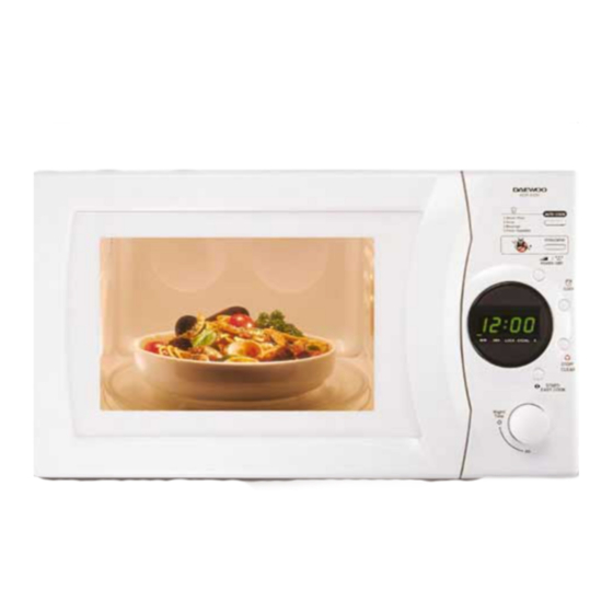
Page 5: External View
EXTERNAL VIEW 1. OUTER DIMENSION(KOR-633R/KOR-863R) 365/392 465/495... -
Page 6: Feature Diagram
EXTERNAL VIEW 2. FEATURE DIAGRAM 1. Safety interlock system 2. Door screen - Allows viewing of food. The screen is transparent to light, but prevents microwaves escaping. 3. Door hook - When the door is closed, it will automatically shut off. If the door is opened while the oven operating, the magnetron tube will immediately stop operating. -
Page 7: Control Panel
EXTERNAL VIEW 3. Control panel 1. Auto cook - Used to cook using a program or to reheat. 2. Defrost - Used to defrost foods by weight or time. 3. Power - Used to set power level. 4. Clock - Used to set clock. 5. -
Page 8: Installation
INSTALLATION 1. Steady, flat location This microwave oven should be set on a steady, flat surface. This microwave oven is designed for counter top use only. 2. Leave space behind and side All air vents should be kept a clearance. If all vents are covered during operation, the oven may overheat and, eventually, cause oven failure. -
Page 9: Operations And Functions
OPERATIONS AND FUNCTIONS 1. Connect the main lead to an electrical outlet. 2. After placing the food in a suitable container, open the oven door and put it on the glass tray. The glass tray must always be in place during cooking. 3. -
Page 10: Disassembly And Assembly
DISASSEMBLY AND ASSEMBLY Cautions to be observed when trouble shooting. Unlike many other appliances, the microwave oven is high-voltage, high-current equipment. It is completely safety during normal operation. However, carelessness in servicing the oven can result in an electric shock or possible danger from a short circuit. - Page 11 DISASSEMBLY AND ASSEMBLY 1. To remove cabinet 1) Remove three screws on cabinet back. 2) Push the cabinet backward. 2. To remove door assembly 1) Remove screws which secure the stopper hinge top. 2) Remove the door assembly from top plate of cavity. 3) Reverse the above for reassembly.
- Page 12 DISASSEMBLY AND ASSEMBLY 3. To remove door parts. (1) KOR-633R0S REF NO. PART CODE PART NAME DESCRIPTION Q’ TY REMARK 3512203860 FRAME DOOR ABS SG-175 3517005630 BARRIER-SCREEN*O 3515204100 STOPPER HINGE*T AS KOR-63150S 3511705500 DOOR WELD AS KOR-61150S 3517002800 BARRIER-SCREEN*I POLYESTER T0.1...
- Page 13 DISASSEMBLY AND ASSEMBLY (1) Remove the gasket door from door plate. (2) Remove the barrier screen inner from door plate. (3) Remove the door frame from door plate. (4) Remove the stopper hinge top from door plate. (5) Remove the spring and the hook. (6) Remove the supporter barrier screen outer from door frame.
- Page 14 DISASSEMBLY AND ASSEMBLY 5. To remove control panel parts. (1) KOR-633R0S REF NO. PART CODE PART NAME DESCRIPTION Q'TY REMARK 3515501540 WINDOW DISPLAY PMMA 3516723730 CONTROL PANEL ABS SG-175 3516907530 BUTTON FUNCTION * A ABS SG-175 3516907540 BUTTON FUNCTION * B...
- Page 15 DISASSEMBLY AND ASSEMBLY 1) Remove the screw which secure the control panel, push up two snap fits and draw forward the control panel assembly. 2) Remove the door open lever from thee control panel. 3) Remove four screws which secure the PCB assembly. 4) Disconnect membrane tail from theconnector of the PCB assembly.
- Page 16 DISASSEMBLY AND ASSEMBLY 8. To remove wind guide assembly. 1) Remove a screw for earthing. 2) Remove the noise filter from the wind guide. 3) Remove a screw which secure the wind guide assembly. 4) Draw forward the wind guide assembly. 5) Pull the fan from the motor shaft.
-
Page 17: Interlock Mechanism And Adjustment
INTERLOCK MECHANISM AND ADJUSTMENT The door lock mechanism is a device which has been specially designed to completely eliminate microwave radiation when the door is opened during operation, and thus to perfectly prevent the danger resulting from the leakage of microwave. Hook Primary interlock... -
Page 18: Trouble Shooting Guide
TROUBLE SHOOTING GUIDE Following the procedure below to check if the oven is defective or not. 1. Check grounding before trouble checking. 2. Be careful of the high voltage circuit. 3. Discharge the high voltage capacitor. 4. When checking the continuity of the switches, fuse or high voltage transformer, disconnect one lead wire from these parts and check continuity with the AC plug removed. - Page 19 TROUBLE SHOOTING GUIDE CONDITION CHECK RESULT CAUSE REMEDY Replace Check continuity of Defective Outlet has magnetron Continuity magnetron proper voltage Fuse does not blow. Check continuity of Replace Defective line noise filter board Continuity filter board Open power Replace Check continuity of power supply cord supply cord Continuity...
- Page 20 TROUBLE SHOOTING GUIDE (TROUBLE 3) No microwave oscillation even though fan motor rotates. CONDITION CHECK RESULT CAUSE REMEDY No Continuity No microwave Check continuity of high oscillation voltage fuse Replace high voltage fuse Replace Continuity Defective Check continuity of high high voltage voltage capacitor transformer...
- Page 21 TROUBLE SHOOTING GUIDE (TROUBLE 4) The following visual conditions indicate a profective touch control circuit or membrane switch assembly. 1. Incomplete segments, 1) Segments missing. 2) Partical segments missing. 3) Digit flickering other than normal display slight flickering. 4) “ :0” does not display when power is on. 2.
-
Page 22: Measurement And Test
MEASUREMENT AND TEST 1. MEASUREMENT OF THE MICROWAVE POWER OUTPUT Microwave output power can be checked by indirectly measuring the temperature rise of a certain amount of water exposed to the microwave as directed below. PROCEDURE 1. Microwave power output measurement is made with the microwave oven supplied at rated voltage and operated at its maximum microwave power setting with a load of 1000 5cc of potable water. -
Page 23: Microwave Radiation Test
MEASUREMENT AND TEST 2. MICROWAVE RADIATION TEST WARNING 1. Make sure to check the microwave leakage before and after repair of adjustment. 2. Always start measuring of an unknown field to assure safety for operating personnel from microwave energy. 3. Do not place your hands into any suspected microwave radiation field unless the safe density level is known. 4. -
Page 24: Component Test Procedure
MEASUREMENT AND TEST 3. COMPONENT TEST PROCEDURE High voltage is present at the high voltage terminal of the high voltage transformer during any cooking cycle. It is neither necessary nor advisable to attempt measurement of the high voltage. Before touching any oven components or wiring, always unplug the oven from its power source and discharge the capacitor. 1. -
Page 25: Wiring Diagram
WIRING DIAGRAM... -
Page 26: Printed Circuit Board
PRINTED CIRCUIT BOARD 1. CIRCUIT CHECK PROCEDURE 1. Low voltage transformer check The low voltage transformer is located on the P.C.B. Measuring condition : Input voltage : 230V / Frequency : 50Hz Terminal Voltage LOAD NO LOAD 4 - 7 AC 12.6 AC 14.7V NOTE... - Page 27 PRINTED CIRCUIT BOARD...
- Page 28 PRINTED CIRCUIT BOARD...
- Page 29 PRINTED CIRCUIT BOARD 3. When there is no microwave oscillation 1) When touching START pad, oven lamp does not turn on. Fan motor do not rotate, but cook indicator in display comes on. * Cause : RELAY 2 does not operate. refer to Circuit Diagram (Point 3) - Check method POINT...
-
Page 30: Circuit Diagram
PRINTED CIRCUIT BOARD 2. P.C.B. CIRCUIT DIAGRAM... -
Page 31: Location No
PRINTED CIRCUIT BOARD 3. P.C.B. LOCATION NO (1) KOR-633R0S NAME SYMBOL SPECIFICATION PART CODE Q’ TY BUZZER BM-20K 3515600100 C ARRAY 5P(4) 102M 50V CN4XB-102M C ELECTRO 16V RSS 100uF CEXF1C101V C ELECTRO 25V RSS 1000uF CEXF1E102V CONNECTOR WAFER CN2... - Page 32 PRINTED CIRCUIT BOARD (2) KOR-863R0S NAME SYMBOL SPECIFICATION PART CODE Q’ TY BUZZER BM-20K 3515600100 C ARRAY 5P(4) 102M 50V CN4XB-102M C ELECTRO 16V RSS 100uF CEXF1C101V C ELECTRO 25V RSS 1000uF CEXF1E102V CONNECTOR WAFER CN2 YW396-02AV 3519150520 CONNECTOR WAFER CN3 YW396-05AV 3519150510 CONNECTOR WAFER CN1...
-
Page 33: Exploded View And Parts List
EXPLODED VIEW AND PARTS LIST 1. DOOR ASSEMBLY Refer to Disassembly and assembly. 2. CONTROL PANEL ASSEMBLY Refer to Disassembly and assembly. 3. TOTAL ASSEMBLY... - Page 34 EXPLODED VIEW AND PARTS LIST (1) KOR-633R0S PART CODE PART NAME DESCRIPTION Q’ TY 3511712170 DOOR AS KOR-63350S 3516720990 CONTROL-PANEL AS KOR-633R0S 3510801310 CABINET PCM T0.36 GE 7112401011 SCREW TAPPING T1 TRS 4X10 MFZN 3516109000 CAVITY WELD AS KOR-63150S 3516119600...
- Page 35 EXPLODED VIEW AND PARTS LIST PART CODE PART NAME DESCRIPTION Q’ TY 3518905300 THERMOSTAT OFF:75 ON:65 H #187 NB 3513003400 HOLDER THERMOSTAT 3516003700 SPECIAL SCREW TT3 HEX 4X8 FLG MFZN 3511406200 COVER WAVE GUIDE HEATPROOF PP 3717400620 COUPLER XAREC 3514700710 ROLLER TEFLON 3512517300...
- Page 36 EXPLODED VIEW AND PARTS LIST (2) KOR-863R0S PART CODE PART NAME DESCRIPTION Q’ TY 3511712170 DOOR AS KOR-86350S 3516720990 CONTROL-PANEL AS KOR-863R0S 3510801310 CABINET PCM T0.36 GE 7112401011 SCREW TAPPING T1 TRS 4X10 MFZN 3516109000 CAVITY WELD AS KOR-86150S 3516119600 CAVITY JOINT AS KOR-86150S 7122401211...
- Page 37 EXPLODED VIEW AND PARTS LIST PART CODE PART NAME DESCRIPTION Q’ TY 3518905300 THERMOSTAT OFF:75 ON:65 H #187 NB 3513003400 HOLDER THERMOSTAT 3516003700 SPECIAL SCREW TT3 HEX 4X8 FLG MFZN 3511406200 COVER WAVE GUIDE HEATPROOF PP 3717400620 COUPLER XAREC 3514700710 ROLLER TEFLON 3512517300...
- Page 38 DAEWOO ELECTRONICS CO., LTD 686, AHYEON-DONG MAPO-GU SEOUL, KOREA C.P.O. BOX 8003 SEOUL, KOREA TELEX : DWELEC K28177-8 CABLE : “ DAEWOOELEC” FAX : 02)360-7877 TEL : 02)360-7804 E-mail : jnpark@web.dwe.co.kr PRINTED DATE : MAR. 2000...
Need help?
Do you have a question about the KOR-633R0S and is the answer not in the manual?
Questions and answers