
Related Manuals for Velleman DVM645BI


Summary of Contents for Velleman DVM645BI
- Page 1 DVM645BI BENCH MULTIMETER TAFELMULTIMETER MULTIMETRE DE TABLE BANCO MULTÍMETRO TISCHMULTIMETER User Manual Gebruikershandleiding Manuel d'utilisation Gebrauchsanleitung...
- Page 2 DVM645BI – BENCH MULTIMETER Introduction This manual contains instructions and warnings that must be observed to ensure safe operation and to keep the meter in a safe condition. WARNING READ "SAFETY INFORMATION" BEFORE USING THE BENCH MULTIMETER This multimeter is a portable 4000-count instrument that is designed for use in the laboratory, the field, at home, and in other environments.
- Page 3 This product complies with the requirements of the following European Community Directives: 89/336/EEC (EMC) and 73/23/EEC (LVD) as amended by 93/68/EEC (CE marking). DVM645BI...
-
Page 4: Chapter 1 A Quick Tour
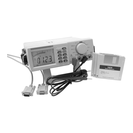
Explanation of Symbols Attention ! Refer to the operating instructions Dangerous voltage may be present at terminals Ground (Earth Terminal) AC - Alternating Current DC - Direct Current Audible Continuity Equipment protected throughout by Double Insulation (Protection Class II) DVM645BI... - Page 5 Instrument Layout Figure 1-1. Bench Multimeter (Front) Figure 1-2. Bench Multimeter (Back) DVM645BI...
- Page 6 AC voltage value as the mains before connecting the power lead to the mains and switching on. This switch is used to turn the AC Power on and off. When the AC Power is on, the DC Power is automatically switched off. 10. The Power Switch DVM645BI...
- Page 7 And the range will also change if it is in auto range. Delay Data Hold: DELAY HOLD Button Press the button to toggle in and out of the Data Hold mode, and the " " indicator turns on or off. DVM645BI...
- Page 8 The frequency measurement is always set to the auto range. The continuity, diode, ADP, DC A and AC A measurements are always set to the manual range. When the power is turned on, the default range is selected. DVM645BI...
- Page 9 5. When the mode is changed from manual to auto range by operating the button. Please refer to the timing chart for the timing. Low Battery Indication The " " indicator is displayed when the battery voltage falls below the reliable operating level. DVM645BI...
-
Page 10: Chapter 2 Measurements
(excessive dirt, grease, etc.) and defects. Examine the test leads for cracked or frayed insulation and make sure the lead plugs fit snugly into the multimeter sockets. If there are any abnormalities, do not attempt to do any measurements. DVM645BI... - Page 11 A minus sign on the left-hand side of the LCD will appear if the leads are connected the other way around. 6. When all measurements have been completed, disconnect the test leads from the circuit under test. Remove the test leads from the multimeter. DVM645BI...
- Page 12 4. Connect the test leads in parallel with the circuit to be measured. Be careful not to touch any live conductors with your hands. Note the reading. 5. When all measurements have been completed, disconnect the test leads from the circuit under test. Remove the test leads from the multimeter. DVM645BI...
- Page 13 3. Switch on the power to the circuit under test. Note the reading. 4. After completing the measurement, turn off the power to the circuit under test, disconnect the test leads from the multimeter. 5. The DC and AC Amps measurements are always fixed range. DVM645BI...
- Page 14 4. Switch on the power to the circuit under test. Note the reading. 5. After completing the measurement, turn off the power to the circuit under test, disconnect the test leads from the multimeter. 6. The DC and AC Milliamps measurements are always fixed range. DVM645BI...
- Page 15 Hz input terminals respectively. 2. The ADP voltage is supplied to the multimeter directly. The result is displayed on a scale of 10 units per 1mV. 3. The ADP measurement is always fixed range. The full range is 400mV DC. DVM645BI...
- Page 16 6. Residual charge in the capacitor, or capacitors with poor insulation resistance or poor dielectric absorption may cause measurement errors. NOTE: A safe way to discharge a capacitor is to connect a 100kΩ resistor across the two capacitor leads. DVM645BI...
- Page 17 4. The typical voltage drop should be about 0.6V for a silicon diode or 0.3V for a germanium diode. 5. If the diode is reverse biased or there is an open circuit and the reading will be between 3.000V and 3.400V. 6. The Diode test is always fixed range. DVM645BI...
- Page 18 Any voltage present during a resistance measurement will cause inaccurate readings and could damage the meter if the overload protection of 250V DC or AC rms is exceeded. 5. Open circuits will be displayed as an overload condition and the MSD (Most Significant Digit) will blink. DVM645BI...
- Page 19 4. An audible tone will sound when the resistance is less than approximately 40Ω. 5. After the continuity measurement has been completed, disconnect the test leads from the circuit and multimeter input terminals. 6. The continuity measurement is always fixed range. Open circuit voltage is approximately 0.45V. DVM645BI...
-
Page 20: Chapter 4 Specifications
Back light Safety: Power requirements Size Weight Accuracy is given as ± (% of reading + number of least significant digit) at 18°C to 28°C, with relative humidity up to 75%. All specifications assume less than 1 year since calibration. DVM645BI... -
Page 21: Resolution And Accuracy
± (0.8% rdg + 5d) 10mA ± (1.5% rdg + 10d) (20A for 30 seconds) Input protection: 1A/250V fuse for mA input, 15A / 250V fuse for A input Load voltage: 600mV max. for mA input, 900mV max. for A input DVM645BI... - Page 22 40MΩ 10kΩ Open circuit Voltage: 0.45V Input protection: 250V RMS Continuity Test Continuity threshold: approx. 40Ω Continuity threshold: 2kHz buzzer tone Input protection: 250V RMS Diode Test Test current: 0.6mA Open circuit voltage: approx. 3.0V Input protection: 250V RMS DVM645BI...
- Page 23 Accuracy: ± (0.1% + 4d) Sensitivity: 100mV rms for 1Hz to 20kHz, 500mV rms for 20kHz to 1MHz Input protection: 250V RMS Adaptive Range Display: 10 units per 1mV DC Accuracy: ± (0.3% + 5d) Input protection: 250V RMS DVM645BI...
-
Page 24: Chapter 4 Maintenance
Two types of battery are used in the bench multimeter: one is a NEDA 1604 6F22 006P type x 1 or equivalent 9V battery, the other is IEC LR6 AM3 AA 1.5V x 6. Never use the bench multimeter unless the battery cover is in place and properly fastened. DVM645BI... -
Page 25: Power Fuse Replacement
Disconnect the test leads from any live source, turn the rotary switch to off, and remove the test leads from the input terminals. Replace the power fuse in the power supply input. Replace the blown fuse with one of the same rating. The power fuse is 80mA/250V, Fast, Ø 5 x 20mm DVM645BI... -
Page 26: Other Notes
Other notes Do not use abrasives or solvents on the bench multimeter, use a damp cloth with mild detergent only. If any faults or abnormalities are observed, the bench instrument should not be used and needs to be inspected. DVM645BI...
Need help?
Do you have a question about the DVM645BI and is the answer not in the manual?
Questions and answers