
Related Manuals for Velleman DVM66


Summary of Contents for Velleman DVM66
-
Page 1: Digital Multimeter
DVM66 Dual Display Digital Multimeter OPERATION MANUAL GEBRUIKERSHANDLEIDING MANUEL D’UTILISATEUR IEC-1010... -
Page 2: Safety Information
DVM66 Dual Display Digital Multimeter 1 Safety information This multimeter has been designed according to IEC-1010 concerning electronic measuring instruments with an over voltage category (CAT II) and pollution 2. Follow all safety and operating instructions to ensure that the meter is used safely and is kept in good operating condition. -
Page 3: Maintenance
• Never use the meter unless the back cover is in place and fastened fully. • To clean the meter, use a damp cloth and mild detergent only, do not use abrasives or solvents on it. VELLEMAN... -
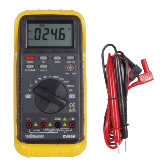
Page 4: Panel Configuration
2.1 Panel configuration LCD Display ô Function buttons o Record o Rel o Range o A-H o AC-DC/ o Hz/∆ % í Rotary Switch ÷ V/Ω/F Input Jack û COM Input Jack ø mA input Jack ù 10A Input Jack VELLEMAN... -
Page 5: Record Button
- Secondary display shows the recording time. At the first minute display shows seconds and then only minutes and hours. - This meter starts to record the max. and min. value measured and calculate the average automatically. VELLEMAN... -
Page 6: Rel Button
- Main display shows the relative percent value. Relative percent value = Rel. Value/reference x 100 % - Secondary display remains the reference value. - Bargraph shows the percentage tolerance specified. • If measurement result is within the tolerance range, built-in buzzer will sound. VELLEMAN... -
Page 7: Range Button
• New value mentioned above means a value much different from the old. In most of measurements with this meter, 10 digit difference is enough. But in resistance measuring, maybe less than 20 digits will not result in a new holding. VELLEMAN... - Page 8 The main display will show the AC voltage value of input signals. At the same time, the frequency of inputs will appear on the secondary display. • In relative value measurement mode, this button is used to specify the percentage tolerance as described in paragraph 2.3. VELLEMAN...
-
Page 9: Input Jacks
DCA or ACA measuring mode. 3. Connect test leads in series with the load in which the current is to be measured. 4. Read LCD display. The polarity of red lead connection will be indicated when making a DC measurement. VELLEMAN... -
Page 10: Measuring Resistance
2. Set the function switch at the FREQ. Position and connect test leads across the source or load under measurement. NOTE : The input voltage should be between 1V and 10V rms ac. If the voltage is more than 10V rms, reading may be out of the accuracy range. VELLEMAN... -
Page 11: Continuity Test
To extend the battery life, Auto Power Off function is provided. If no key operations or range changing happen for 20 to 40 minutes (According to the function selected), the meter will be turned off automatically. To turn it on, rotate the rotary switch or push any function buttons only. VELLEMAN... -
Page 12: Specifications
+ 0.5% of rdg + 2 digits 10mV + 0.5% of rdg + 2 digits 400V 0.1V + 0.5% of rdg + 2 digits 1000V + 0.5% of rdg + 2 digits Input impedance : 10MΩ, more than 100MΩ at 400mV range. VELLEMAN... - Page 13 + 3.0% or rdg + 5 digits 0.05V/A Overload Protection : F 500mA fuse for mA ranges, F 10A fuse for A range. Frequency range : 40 to 400 Hz. Response : Average, calibrated in rms of sine wave. VELLEMAN...
- Page 14 4.8 CAPACITANCE Range Resolution Accuracy 40nF 0.01nF + 2.0% of rdg + 5 digits 400nF 0.1nF + 2.0% of rdg + 5 digits 4µF + 2.0% of rdg + 5 digits 40µF 10nF + 2.0% of rdg + 5 digits VELLEMAN...
-
Page 15: Supplied With The Multimeter
Hang the meter on the wall using the little stand. Take the little stand off from the back side of the large stand and insert it into holes located upper on the holster. d. Hold test leads. Fig. a Fig. b Fig. c Fig. d VELLEMAN... -
Page 16: Battery And Fuse Replacement
Before attempting to open the case, be sure that test leads have been disconnected from measurement circuit to avoid electric shock hazard. For protection against fire, replace fuses only with specified ratings : F1 : F 500mA/250V F2 : F 10A/250V VELLEMAN...
Need help?
Do you have a question about the DVM66 and is the answer not in the manual?
Questions and answers