Advertisement
Quick Links
Instruction Manual
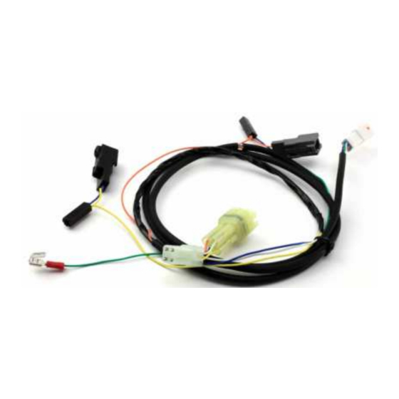
DialDim™ Wiring Harness
Kawasaki KLR650
DNL.WHS.21900
OUTFITTING
GUIDE
What's In The Box?
(a) DialDim™ Wiring Harness.....................................................Qty 1
DENALIELECTRONICS.COM
Instruction Rev00
Thank you for choosing DENALI
We know you would rather be riding your bike than wrenching on it, so we go the extra
mile to make sure our instructions are clear and as easy to understand as possible. If
you have any questions, comments, or suggestions don't hesitate to give our experts
a call at 401.360.2550 or visit WWW.DENALIELECTRONICS.COM
Please Read Before Installing
DENALI products should always be installed by a qualified motorcycle technician. If
you are unsure of your ability to properly install a product, please have the product
installed by your local motorcycle dealer. DENALI takes no responsibility for damages
caused by improper installation. Caution: When installing electronics it is extremely
important to pay close attention to how wires are routed, especially when mounting
products to the front fender, front fork, or fairing of your motorcycle. Always be sure
to turn the handlebars fully left, fully right, and fully compress the suspension to
ensure the wires will not bind and have enough slack for your motorcycle to operate
properly.
Installation Tips
We strongly recommend using medium strength liquid thread locker on all screws and
bolts. It is also important to ensure that all hardware is tightened to the proper torque
specifications as listed in your owner's manual. For included accessory hardware
please refer to the default torque specifications provided below. Inspect all hardware
after the first 30 miles to ensure that proper torque specifications are maintained.
Bolt Size
in-lbs
M3
10.0 in-lbs
23.0 in-lbs
M4
M5
44.5 in-lbs
M6
78.0 in-lbs
M8
-
M10
-
M12
-
Hardware Sizing Guide
Not sure what size bolt you have? Use this ruler to measure screws, bolts, spacers, etc.
Remember, the length of a screw or bolt is measured from the start of the "mounting
surface" to the end of the screw, so only include the screw head when measuring
countersunk screws.
0
10
20
30
mm
0
1
in
ft-lbs
Nm
-
1.0 Nm
-
2.5 Nm
3.5 ft-lbs
5.0 Nm
6.5 ft-lbs
9.0 Nm
13.5 ft-lbs
18.0 Nm
30.0 ft-lbs
41.0 Nm
52.0 ft-lbs
71.0 Nm
40
50
60
70
2
3
80
90
Advertisement

Related Manuals for Denali DialDim


Summary of Contents for Denali DialDim
- Page 1 401.360.2550 or visit WWW.DENALIELECTRONICS.COM Please Read Before Installing DENALI products should always be installed by a qualified motorcycle technician. If you are unsure of your ability to properly install a product, please have the product installed by your local motorcycle dealer. DENALI takes no responsibility for damages caused by improper installation.
- Page 2 + (Red Terminal). area of the seat and begin routing the battery leads towards the battery. Step Five: Remove the fuse from the DialDim fuse holder, then connect both of the battery leads to the battery, starting with the ground - (Black Terminal).
- Page 3 Signal Connector 3.1 - Locating Connectors & Installing the Harness The KLR650 DialDim Harness will be connected in-line to the four following Step Three: The right turn signal connector is located inside the upper factory harness connectors: Headlight, Right Turn Signal, Left Turn Signal fairing, just behind the factory turn signal.
Need help?
Do you have a question about the DialDim and is the answer not in the manual?
Questions and answers