Scotsman CU50 Technical Training Manual
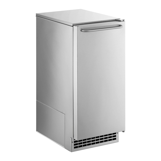
Cube ice machine
Hide thumbs
Also See for CU50:
- Service manual (30 pages) ,
- Installation and user manual (16 pages) ,
- Service bulletin (4 pages)
Advertisement
Quick Links
Advertisement

Subscribe to Our Youtube Channel
Related Manuals for Scotsman CU50


Summary of Contents for Scotsman CU50
- Page 1 Scotsman Technical Training CU50 Cube Ice Machine...
- Page 2 Major Topics • Overview • Installation • Start Up • Sequence of Operation • Maintenance • Diagnostics • Service Procedures...
- Page 3 Models • Two Base Models – Gravity Drain – Pump Drain • 15” wide • 50 lb capacity • Stainless...
- Page 4 Reverse Door Swing • Remove hinge pin • Tip door forward, lift off • Remove hinges • Switch hinges top to bottom & left to right • Place door on bottom pin • Attach with top hinge pin...
-
Page 5: Installation Prep
Installation Prep • Remove back panel • Remove front service panel • If needed, remove kickplate... - Page 6 Installation – Free Standing Gravity Drain • Route water supply tubing to inlet water solenoid valve • Attach drain tubing to bin drain hose – Elbow and hose clamps • Route drain tubing to building drain...
- Page 7 Installation – Built In Gravity Drain • Plan the installation for machine removal – Coil of water supply tubing – Arrange the drain tubing so it does not kink when the machine is pushed into place • Recommended drain tube size is 5/8” ID, 7/8” OD plastic hose •...
- Page 8 Installation – Built In Pump Drain • Remove back panel • Route water supply tubing to inlet water connection on solenoid valve • Route drain hose to building drain...
- Page 9 Water Supply Route Water Supply Tubing ¼” Compression Fitting...
- Page 10 Operation – Initial Start Up • Remove shipping materials • Connect water • Check for leaks • Connect power • Push and release the On / Off button...
-
Page 11: Sequence Of Operation
Sequence of Operation • Inlet water solenoid valve opens to fill the reservoir • Hot gas valve opens to equalize the system • Compressor, fan and pump start • Hot gas valve closes, freeze cycle begins • Freeze cycle continues until evaporator temperature reaches a preset point - 0, which triggers a 10 minute (default) timer •... - Page 12 Sequence of Operation - Harvest • Hot gas valve opens • Pump and Fan motor stop • Inlet water valve opens and refills the reservoir – Fill time varies with evaporator temperature • Timed during a power restart or in clean cycle •...
- Page 13 Harvest Details • 24 individual cubes per cycle • Hot gas defrost with a water assist • Water flows onto top of evaporator platen to – Warm up the platen & obtain a faster harvest – Remove heat from the water for the next cycle...
-
Page 14: Control System
Control System • Electronic controller • Operates – 12 volt power supply – Compressor – Evaporator thermistor – Pump – Water quality sensor – Fan motor – Bin thermostat – Hot gas valve coil – Inlet water solenoid valve coil... - Page 15 Mechanicals Curtain Bracket Fastener Curtain...
- Page 16 Controller Evaporator Thermistor Hi Voltage Connector Comp Bin Thermostat Water Water Sensor Hot Gas Power Power Supply Connector Control Panel Ribbon Cable...
- Page 17 Controls On – Off Button Used in Green when set Blinks Red if out Yellow if its been 6 cleaning of water to ice making months since it was process cleaned...
- Page 18 Control Operation – Check Water • Red blinking light indicates a lack of water • Water must fill reservoir within 2 minutes • Unit automatically re-tries filling the reservoir every 20 minutes...
-
Page 19: Control Details
Control Details • Maximum freeze time: 60 minutes – Automatically harvests after 60 minutes of freeze • Maximum harvest time: 6 Minutes • Time between restarts: 4 minutes • Power interruption restart: – Timed harvest cycle to clear ice... - Page 20 Control Details – Water Sense • Water conductivity varies by mineral content – More minerals = more conductivity • Control system senses conductivity, varies water use to rinse more water if there is high conductivity, reducing mineral build up potential •...
- Page 21 Control Details – Ice Level • Controlled by bin thermostat in cap tube / scoop holder • When bin thermostat senses ice, contacts open, signaling controller to shut down – If suction line temperature is above preset point, unit shuts off –...
-
Page 22: Bin Thermostat Adjustment
Bin Thermostat Adjustment • Adjustment screw located behind cover • Ambient compensation adjustment: – Rotate CW to raise ice level – Rotate CCW to lower ice level... - Page 23 Mechanicals Transformer Refrigerant Outlet Refrigerant Inlet Controller Water Inlet Evaporator Platen...
- Page 24 Mechanicals – Evaporator • 24 copper cups...
- Page 25 Water Spray – 6 Jets...
- Page 26 Mechanicals Water Pump Water Tube Suction Line & Accumulator Compressor Bin Drain...
- Page 27 Mechanicals...
- Page 28 Mechanicals – In Reservoir Spray Platform 50 lb Water Sensor Water Inlet Probes Connection Overflow Water Pump Body Standpipe...
- Page 29 Mechanicals • Spray platform removable – Lift up to release platform from water inlet connection – Pull out...
- Page 30 Control Operation – Time to Clean • Glowing yellow light comes on after 6 months of power up time • Cleared by going through the cleaning process – Press and Hold the Clean button for 3 seconds...
-
Page 31: Maintenance
Maintenance • Air cooled condenser – service frequently when pets are in the house – Remove service panel – Remove kickplate – Vacuum condenser... - Page 32 Maintenance • Water System – Clean with scale remover – Check curtain – Check spray jet pattern • 6 jets • Platform lifts out...
- Page 33 50 lb Maintenance – Scale Remover • Remove all ice • Push and hold the On/Off button in for 3 seconds until the green light goes out • Press and HOLD the both the Clean-Reset and On/Off buttons for 5 seconds. The Time to Clean light will blink on and off.
- Page 34 Scale Remover - continued • Pour in 8 ounces of Scotsman Scale Remover. • Operate the machine for a half hour. • Push and release the ON/OFF switch to start the rinsing process. • Operate the machine for another half hour.
- Page 35 Maintenance • Spray jet caps are removable – clean separately if needed – Remove spray platform – Remove nuts (7/32”) – Pull jet caps off...
- Page 36 Maintenance • Clear nozzle of debris • O-ring must be in correct position and undamaged...
- Page 37 Maintenance • Optional: drain reservoir – Remove cap on bottom of reservoir – Clean cap of debris...
-
Page 38: Service Diagnosis
Service Diagnosis • The Recipe for Ice: – Add Water – just the right amount – Apply strong amount of Refrigeration effect to take heat from the water & release the ice – Use an Electrical System to Operate and Control the machine to deliver ice when its needed –... - Page 39 Service Diagnosis • No ice, check: – Switched off – push & release ON/OFF button – Power to unit – on/off light on after switching on? – Bin thermostat – contacts open? – Water in reservoir – water light blinking? •...
- Page 40 Service Diagnosis • No ice, water in reservoir, but no spray – Check water pump • No ice, water in reservoir, sprays, ice forms but harvest cycle does not start – Check evaporator thermistor – Use ohmmeter, check resistance for the sensor’s temperature •...
- Page 41 Service Diagnosis • Makes ice, but cubes are mal-formed – Check for clogged / restricted spray jets – Check if running out of water before the end of the freeze cycle • Check for water leak – Clean as required...
- Page 42 Service Diagnosis • Makes ice, but customer indicates low capacity – Check cycle time – 50 lb times: • 70 air, 50 water cycle time is about 20 minutes • 90 air, 70 water cycle time is about 28 minutes •...
- Page 43 Service Diagnosis • Makes ice, some (8-10) cubes are malformed – Check cycle time • 21+ minute freeze • 4-5 minute harvest • Cubes fully formed in evaporator, but are malformed when harvested • All the above indicates a low refrigerant charge...
-
Page 44: Refrigeration System
Refrigeration System • Normal Operating System – Suction pressure • Beginning freeze rapid pull down to: 20 PSIG • End of freeze: 1 - 2 PSIG • Harvest: increases from 30 to 55 PSIG • Low charge – Suction pressure •... - Page 45 Service Diagnosis • Makes ice, but cubes are shells – Check for shortage of water – If water supply is adequate, adjust cube size by changing freeze time • Makes ice, but cubes are too large – Freeze cycle is too long –...
- Page 46 Control Adjustments – Cube Size 1. Shut unit off 2. Hold in 5 sec or until 3. Push & release once Yellow light goes out to check setting Minutes Ice making Check water Time to clean 5. Push and release to 4.
- Page 47 Service Diagnosis • No ice, freezes, harvest begins but evaporator does not defrost – Hot gas valve not opening – Check coil, replace if open – Check voltage to coil, if 115 volts, and coil is not open, hot gas valve is stuck and must be replaced.
- Page 48 Service Diagnosis • Freezes ice, harvest begins, fan motor stops, pump stops, water valve opens, hot gas valve opens but will not harvest all cubes – Connected to very cold water • Harvest time set too short • Adjust harvest time...
- Page 49 Control Operation – Manual Harvest 1. Shut unit off 2. Push and Hold in for 5 • All lights flash once. seconds, then release. • Ice Making Light switches ON 3. Wait 5 - 20 seconds 4. Push and Hold in for 5 •...
- Page 50 Control Adjustments – Harvest Time 1. Shut unit off 3. Push and release to 2. Hold in until blue light change to next level goes out Seconds Ice making Check water Time to clean 4. Push and release to Default confirm the displayed setting 5.
- Page 51 Service Diagnosis • Yellow Clean light is on – It’s been a long time since it was cleaned – Clean the machine per the published method, the light will go out – Or – Advise user to press and hold the clean button for 3 seconds...
- Page 52 Service - Remove Cabinet • Drain reservoir • Disconnect water, power and drain • Remove door Thermistor • Remove back panel Connection • Remove top panel • Remove control box cover • Disconnect thermistor at controller, pull wire to back of unit •...
- Page 53 Service – Remove Cabinet • Remove evaporator water inlet connection – Remove clip Remove from here – Pull hose & elbow from inner elbow – Push inner elbow back – Rotate inner elbow up – Push out of wall Inner Elbow...
- Page 54 Service – Remove Cabinet • Remove service panel • Remove kickplate • Remove air baffle Air Baffle • Remove 4 bottom corner screws • Pull bin thermostat cap tube from holder – handle carefully Bottom Corner Screw...
- Page 55 Service – Remove Cabinet • Lift front brace up Front Brace • Separate the 7 wire harness connectors – located by suction line • Tip evaporator & suction line assembly back enough to clear the cabinet...
- Page 56 Service – Remove Cabinet • Lift cabinet off of base – Pump, bin stat and controller go with cabinet – Support evaporator while cabinet is off • Use 3 foot ¾” PVC tube from evaporator cube cell to base Prop Tube...
- Page 57 Summary • 15 inch cabinet • Clear ice • Individual cubes • R-134a • 50 lb - simple circuit board, limited complexity...
Need help?
Do you have a question about the CU50 and is the answer not in the manual?
Questions and answers