Table of Contents
Advertisement
Quick Links
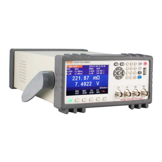
JK2520B/JK2520C
Battery Internal Resistance Tester
4
3/4
Jinko
It is a registered trademark of
JinAiLian Electronic Technology Co.,Ltd
User's Guide
bit AC resistance reading,6 bit DC voltage readings
Resistance test range:0.000mΩ~33.000kΩ
Voltage test range:0.00000V~120.000VDC
0.2% resistance accuracy, 0.01% voltage accuracy.
Test speed up to 145 times / sec.
HANDLER interface(Optional 18 gear sorting)
Technical support e-mail :mailjk17@163.com
RS-232C inerface
JinAiLian Electronic Technology Co.,Ltd
C3, No.22 Building, New Impetus Pioneering
Center, No.1, North Qingyang Road, Tianning
District, Changzhou City
Tel:4001128155
Fax:0519-85565067
Http://www.jaldz.com
Http://www.jk17.com
Sales service e-mail:mailjk17@163.com
1
Advertisement
Table of Contents

Related Manuals for Jinko JK2520B


Summary of Contents for Jinko JK2520B
- Page 1 User’s Guide JK2520B/JK2520C Battery Internal Resistance Tester bit AC resistance reading,6 bit DC voltage readings Resistance test range:0.000mΩ~33.000kΩ Voltage test range:0.00000V~120.000VDC 0.2% resistance accuracy, 0.01% voltage accuracy. Test speed up to 145 times / sec. HANDLER interface(Optional 18 gear sorting)...
-
Page 2: Security Information
Security needs warning DANGER : When you find the following abnormal conditions, please terminate the operation immediately and disconnect the power cord. Contact and repair the Jinke instrument sales department immediately. Otherwise, it will cause a fire or potential danger to the operator.。 Abnormal operation of instrument Abnormal noise, odor, smoke or Flash occurred during operation. -
Page 3: Limited Warranty And Scope Of Liability
Limited warranty and scope of liability Changzhou JinAiLian Electronic Technology Co.,Ltd (hereinafter referred to as JinAiLian ) to ensure that you buy each JK2520B/JK2520C in quality and measurement are fully qualified.This warranty does not include fuses and damage caused by negligence, misuse, pollution, accident or abnormal use. - Page 4 consequential damage or loss (including loss of information) caused by any reason outside the scope of the specification.If one of these clauses contravenes local laws or because certain jurisdictions do not permit the exclusion or restriction of implied warranties, the local laws and regulations prevail, then this clause may not apply to you. However, the ruling of this clause does not affect the validity and enforceability of other provisions.
-
Page 5: Table Of Contents
Catalog Safety instruction ......................1 Security information.......................1 Limited warranty and scope of liability................2 Catalog..........................3 List of Figures .......................6 Table list ........................6 1.Installation and setup wizard ..................7 1.1 Packing list......................7 1.2 Power requirements..................7 1.3 Operating environment..................7 1.4 Clean.......................7 2.Summary........................7 2.1 Introduction...................... 7 2.2The main function..................... - Page 6 6.1.4 [Beep] set up....................20 6.1.5 【baud rate】 set up ................20 6.1.6Communication [instruction handshake] switch........20 6.1.7 Communication [result delivery] mode.............21 6.2System information page ................21 7. Processor (Handler) interface<JK2520B> ............22 7.1 Terminal and signal..................22 7.2 Connection mode ..................23 8. Remote communication..................24 8.1 RS-232C .......................24 8.1.1 RS232C Connect..................25...
- Page 7 9.2.1 Command ....................27 9.2.2 parameters....................27 9.2.3 Separators....................28 9.3 command reference..................28 9.4 DISPlay Display subsystem................29 9.4.1 DISPlay:PAGE ..................29 9.4.2 DISP:LINE ....................29 9.5 FUNCtion subsystem...................29 9.5.1 FUNCtion:RANGe ..................30 9.5.2 FUNCtion:RANGe:MODE.................30 9.5.3FUNCtion:RATE ..................30 9.6 COMParator subsystem................30 9.6.1 COMParator:RMODe ................31 9.6.2COMParator:VMODe.................31 9.6.3 COMParator:BEEP ..................31 9.6.4 COMParator:TOLerance:RNOMinal ............31 9.6.5 COMParator:TOLerance:VNOMinal ............32 9.6.6 COMParator:TOLerance:RLMT ...............32...
- Page 8 10.4 Shape size......................37 List of illustrations Fig. 3-1 front panel ....................10 Fig. 3-2 rear panel ....................10 Figure 4-1 < measurement display> page...............12 Figure 4-2 < browse data > page ................15 Figure 5-1 < Settings > page...................16 Fig. 5-2 the correct short circuit method..............17 Figure 6-1 <...
-
Page 9: Installation And Setup Wizard
If there is any damage or insufficient accessories, please contact JinAiLian sales department or distributor immediately. 1.2 power requirements JK2520B can only be used in the following power supply conditions: Voltage: 85VAC~250VAC Frequency: 50Hz~400Hz Warning: to prevent the danger of electric shock, please connect the power ground. -
Page 10: Introduction
The newly designed AC resistance testing principle can be used for almost all battery internal resistance testing, including lithium battery, lead-acid battery, button battery and other battery pipeline inspection. JK2520B do not support UPS online measurement, JK2520C support UPS online measurement. -
Page 11: Test Frequency
JK2520C:6 range test,30mΩ~30kΩ。 JK2520B: 4 range test,30mΩ~30Ω。 Range automatic, manual and nominal. Range nominal (Jinko new noun definition) : the instrument automatically selects the best range based on the nominal value. 2.2.3 Test speed The instrument is divided into four speeds: slow speed, medium speed, high speed and high speed. -
Page 12: Interface
Absolute value tolerances + TOL sorting:The absolute deviation between the measured value and the nominal value is compared with the limit of each file. Percentage tolerance TOL sorting: The percentage deviation between measured and nominal values is compared with the limit of each file. Sequential comparison sorting: comparison of measured values directly with upper and lower limits 2.2.9 system setup 1. - Page 13 Front panel function description Function display Power switch System function keys Test end USB disk interface Qualified / unqualified Digital keyboard Cursor key Display key 3.1.2 Understanding the rear panel Fig. 3-2 rear panel 1.blowhole 2.Power socket (without fuse, fuse in instrument).
-
Page 14: Starting Up
3.2 power on startup 3.2.1 starting up 3.3 Connection of test end If you use a random "Kelvin" test clip for testing, connect to the instrument test end in the following manner. High frequency head does not distinguish between Drive and Sense terminals, the instrument will automatically convert. -
Page 15: Trigger Mod
Trigger – trigger mode Range - Test Range Speed - test speed Alarm - comparator alarm alarm Figure 4 -1 < measurement display> page Slow, medium speed and fast mode High speed mode [Trigger] mode 4.1.1 SCPI Command: TRIGger:SOURce {INT,MAN,EXT,BUS} SCPI Query Command: TRIGger:SOURce? The instrument has 4 triggering modes: Internal triggering, manual triggering, external triggering and remote triggering. -
Page 16: Range
100Ω 32Ω~330Ω 10Ω 3.2Ω~33Ω 1Ω 320mΩ~3.3Ω 100mΩ 32mΩ~ 330mΩ 10mΩ <33mΩ JK2520B have 4 ranges. The range of variation for each range is as follows: Table 4‐2 Range of change Range number Range name Range 10Ω 3.2Ω~33Ω 1Ω 320mΩ~3.3Ω 100mΩ... - Page 17 SCPI Query Command: FUNCtion:RATE? JK2520C Provide 4 test speeds (slow, medium speed, fast and high speed). JK2520B Provide three test speeds (slow, medium, fast), the slower the test results are more accurate and stable. In the manual range mode, the sampling time of the comparator is as follows: Slow: 1 times / sec (1s).
-
Page 18: Status Bar
Speed: 30 times / sec (33ms). High speed: 145 times / sec (6.8ms) (JK2520B) Steps to set test speed are: The first step is to enter the measurement page according to [Meas] or enter the setup page according to [Setup]. -
Page 19: Browse Data] Function Keys
USB The disk is ready. Data is maintained. [Browse data] function keys 4.2.2 According to [browse data] funtion key, enter the< browse data > page. 4.3 [Browse data] page The measurement results on the current screen can be maintained on the Flash disk inside the instrument by the Save Data function key on the Measurement Display page. -
Page 20: Comparator Settings
All the settings related to measurement are operated in < Settings > page. < Settings > page, the instrument does not display test results or comparator results, but the instrument test is still in progress. These settings include the following parameters: Trigger -trigger mode Range - Test Range Speed - test speed... -
Page 21: Nominal Value] Input
Function key Function Close The comparator of the current parameter is closed. Absolute value Switch comparator to absolute value comparison mode. Relative value % Switch comparator to Relative value comparison mode. Direct reading value SEQ Switch comparator to Direct reading value comparison mode. -
Page 22: System Configuration
Before you clear it, please first clip the test clip according to the following methods. Fig 5‐2 Correct short circuit method Short circuit clearing method The first step is to press [ Setup ] to enter the setup page. Second step short test clip The third step is to use function keys to select [short circuit] The fourth step is to press[ confirm]the instrument to start clearing. -
Page 23: Change System Language【Language
Change system language【LANGUAGE】 6.1.1 Communication instruction:SYSTem:LANGuage {ENGLISH,CHINESE,EN,CN} The instrument supports two languages, Chinese and English. Change the language steps The first step is to enter the < system configuration > page. The second step is to use cursor keys to select [LANGUAGE]. The third step is to use the function key selection language: Function key Function... -
Page 24: Account Settings
Minute+ +1 Minute Minute- -1Minute Second + +1 second Second - -1 second 6.1.3 Account Settings There are two user modes to choose from. Administrators Except for the System Services page, other functions are open to administrators, and the parameters set by administrators are stored in system memory after a delay of 5 seconds for loading after the next boot. - Page 25 The third step is to use function key selection. Function key Function Closed Beep closed Qualified beep When the sorting result is qualified (GD), the buzzer calls. Unqualified beep When the sorting result is unqualified (NG), the buzzer calls. 6.1.5 [baud rate] settings The instrument has built-in RS-232 interface.
-
Page 26: System Information Page
The second step is to use the cursor keys to select the[ instruction handshake] field. The third step is to use function keys. Function key Function Close Do not use Command handshake.If there is no special requirement, please set the command handshake closed Open 6.1.7 communication【Result Send out 】mode Communication instruction:SYSTem:SENDmode {FETCH,AUTO}... -
Page 27: Processor (Handler) Interface
7.Processor (Handler) interface<JK2520B> You will learn the following: Wiring terminal How to connect and interface schematics The instrument provides users with a fully functional processor interface, which includes 10 grades of qualified sorted output, HI / IN / LO, EOC (test completion signal), TRIG (external trigger start) input and other signals. -
Page 28: Connection Mode
/V-LO 0:V-LO /R-HI 0:R-HI /R-NG 0:R-NG /R-LO 0:R-LO Input end Tabel 7‐2 Input pin definition Name Explain Trigger Trigger input, built-in 0.25W, 2K, current limiting resistor. The input rising edge is effective. Power terminal Table 7‐3 Power end pin definition Name Explain 27-30... - Page 29 Internal power: 5V Max 1A. Use internal power supply and connect to the following pins.: VCC(5V):34 and 35 short circuit Electrical parameters Power requirements: +3.3V~24VDC Output signal: collector output with built-in pull resistance. Optocoupler isolation. Low level effective. Maximum voltage: supply voltage. Input signal: optocoupler isolation.
-
Page 30: Remote Communication
8.remote communication You will learn the following: Introduction of RS-232 interface RS-232 connection. Select baud rate. Software protocol. The instrument uses RS-232 interface (standard configuration) to communicate with the computer to complete all the functions of the instrument. Through the standard SCPI command, users can easily compile various collection systems suitable for themselves. -
Page 31: Handshake Protocol
receive data Grounding Request to send Besides, RS232 also has the smallest subset, which is the way of connecting the instrument. Table- 8-2 The smallest subset of the RS - 232 standard signal Symbol Pin number of 9 core connector send data receive data Grounding... -
Page 32: Scpi Language
in communication, the instrument can enable software handshake. The high-level language software engineer should compile the computer communication software strictly according to the following handshake protocol: The instrument command parser accepts only ASCII format, and command response also returns ASCII code. The command string sent by the host must end with NL ('\n'), and the instrument command parser does not start executing the command string until it receives the terminator. -
Page 33: Scpi Command Reference
8. SCPI Command Reference This chapter includes the following aspects: Command parser - understand some rules of command parser. Command grammar——Writing rules of command line Query syntax——Writing rules for query commands Query response——Query response format Command Reference This section provides all the SCPI commands used by the instrument, through which all the functions of the instrument can be fully controlled. -
Page 34: 3Command Tree Structure
<> The text in the brackets represents the parameters of the command. The words in square brackets indicate optional commands. When braces contain several parameter items, it means that only one item can be selected from it. The abbreviations of parameters are in parentheses majuscule The abbreviation of command. -
Page 35: Command Reference
For example:AAA:BBB The parameter can be a string form, and its abbreviation rule still obeys the command abbreviation rule of the preceding section. For example:AAA:BBB 1.23 Parameter can be numerical form. <integer> integer 123,+123, -123 <float> Floating-point number 1. <fixfloat>:Fixed point floating point number :1.23,-1.23 2. -
Page 36: Display Display Subsystem
FUNCtion funtion subsystem CORRection correction subsystem COMParator comparator subsystem SYSTem system subsystem TRIGger trigger subsystem FETCh? Get the result subsystem ERRor error message subsystem Public command : IDN? Instrument information inquiry subsystem TRG Trigger and get data SAV Save all settings parameters to internal disk. 9.4 DISPlay display subsystem DISPlay subsystemIt can be used to toggle different display pages or to display a string of text on the page prompt bar. -
Page 37: Function Subsystem
{SLOW,MED,FAST, ULTRA} 9.5.1 FUNCtion:RANGe FUNC:RANG Used to set the range mode and range number. Command grammar:FUNCtion:RANGe {<range number>,min,max} Parameters:among them,<range number> 1~6(JK2520C) 1~4(JK2520B) min range =1 max range =6(JK2520C) 4(JK2520B) For example: Send out > FUNC:RANG 3<NL> //Switch to 3 range.(300mΩ)... -
Page 38: Comparator:rmode
Fig 9‐4 COMParator subsystem tree COMParator :BEEP {OFF,GD,NG} :RMODe {OFF,SEQ,PER,ABS} :VMODe {OFF,SEQ,PER,ABS} :TOLerance RNOMinal <float> VNOMinal <float> RLIMIT(RLMT) <LOWER,UPPER> VLIMIT(VLMT) <LOWER,UPPER> 9.6.1 COMParator:RMODe COMParator:RMODe ,used to set the resistance comparator mode Command grammar:COMParator:RMODEe {OFF,ABS,PER,SEQ} parameter:{OFF,ABS,PER,SEQ} Among them: ABS Absolute value sorting mode PER Percentage sorting mode SEQ Sequential sorting mode For example: Send out >... -
Page 39: Comparator:tolerance:vnominal
Command grammar:COMParator:TOLerance:RNOM <float> For example: Send out > COMP:TOL:NOM 1m //The nominal value is set to 1mΩ Send out > COMP:TOL:NOM 1E-3 //The nominal value is set to 1mΩ Send out > COMP:TOL:NOM 1000 //The nominal value is set to 1mΩ Query syntax:COMP:TOL:RNOM? Query response:<scifloat>... -
Page 40: Trigger[:Immediate]
TRIGger [:IMMediate] :SOURce {INT,MAN,EXT,BUS} TRIGger is used to set trigger source and generate one trigger. 9.7.1 TRIGger[:IMMediate] TRIG[:IMM] When the trigger source is set to BUS, a trigger is generated, but the data that triggers the test is not returned.If you want to return data You need to use the TRG directive. -
Page 41: Correction Subsystem
9.9 CORRection subsystem The CORRection subsystem is used for short circuit zero calibration. Fig 9‐7 SYSTem subsystem tree CORRect :SHORt 9.9.1 CORRection:SHORt Query syntax:CORRection:SHORt For example: Send out >CORRection:SHOR<NL> Return >Short Clear Zero Start. <NL> Return >PASS<NL> Note: Before the Send out command, make sure that the test end is short circuited. 9.10 SYSTem subsystem SYSTem The subsystem is used to set parameters related to the system. -
Page 42: Error Subsystem
IDN?subsystem It is used to return the version number of the instrument. Query syntax:IDN? Query response:<MODEL>,<Revision>,<SN>,< Manufacturer> For example: Send out > IDN? <NL> Return > JK2520C/2520B,REV C1.0,0000000,Applent Instruments<NL> 9.12 ERRor subsystem The error subsystem is used to get the latest error message. Query syntax:Error? Query response:Error string For example: Send out >... - Page 43 ULTRA FAST SLOW Reading 12.000V 100μV 0.5%±100 0.3%±50 0.2%±10 0.2%±5 120.000V 0.5%±100 0.3%±50 0.2%±10 0.2%±5 JK2520B AC resistance indicator: RANGE Max Reading Resolution FAST SLOW Test Current 10mΩ 30.00mΩ 10μΩ 1.5% ± 10 1% ± 5 150mA 100mΩ 300.00mΩ 100μΩ...
-
Page 44: Environmental Requirements
Triggering: internal, external, manual and remote triggering. Interface: processor (Handler) interface, RS232 interface Optional interface: RS485 and USB-232 interface Programming language: SCPI UPS Online measurement: JK2520B do not support UPS online measurement, JK2520C support UPS online measurement. Auxiliary function: keyboard lock 10.3 Environmental requirements Environment: indicators: temperature 18℃~28℃...
Need help?
Do you have a question about the JK2520B and is the answer not in the manual?
Questions and answers