Table of Contents
Advertisement
Advertisement
Table of Contents

Subscribe to Our Youtube Channel
Related Manuals for elsner elektronik Arexa 230V Window Control


Summary of Contents for elsner elektronik Arexa 230V Window Control
- Page 1 Arexa 230V Window Control Item number 10115 Installation and Adjustment...
-
Page 2: Table Of Contents
Description ........................3 Scope of supply ............................. 3 Commissioning procedure ........................3 Options for connection and control ......................3 Overview of available automatic functions .................... 4 Operation ........................5 Key functions and display symbols of the meteorological data display ..........5 Display of lightness and wind speed ..................... - Page 3 Safety instructions for automatic and alarm functions ..............32 A. Indoor temperature for opening ...................... 34 B. Outdoor temperature block ......................35 C. Wind alarm ............................36 Table for wind speeds ......................... 36 D. Rain alarm ............................37 E. Storage of automatic settings ......................38 Service ........................
-
Page 4: Description
Description The Arexa window control system has been developed for the automatic control of a window (or a group of windows) and for comfortable manual operation. The control system offers a highest degree of flexibility for installation and setting and may therefore be adjusted individually to different conditions. -
Page 5: Overview Of Available Automatic Functions
• Wind speed • Precipitation Overview of available automatic functions • Open when a selectable indoor temperature is reached • Close and keep closed below a selectable outdoor temperature (outdoor temperature block) • Open until a programmable position is reached •... -
Page 6: Operation
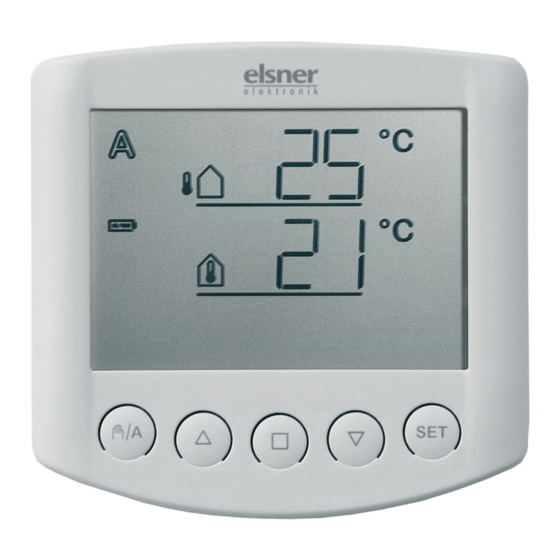
Operation Key functions and display symbols of the meteorological data display Outdoor Temperature Automatic Manual Indoor Temperature Battery Rain alarm Wind alarm Manual/ Stop Down Setting Automatic The basic position of the operating unit of the control system displays the current outdoor temperature (upper line) and the indoor temperature (lower line) as well as the function mode (automatic or manual), the battery load and the current alarm messages for rain or wind. -
Page 7: Display Of Lightness And Wind Speed
Manual mode activated. The connected drive mechanism was operated manually (with arrow keys) or key was pressed. Thus, the automatic functions are deactivated, there is no control in terms of temperature. The safety functions rain alarm and wind alarm are still activated. The control is in manual mode until you change to automatic mode with key. -
Page 8: Move Window Manually
Move window manually Stop Down The connected window may be manually operated with the keys . The arrow keys are provided with a time automatic. By short pressing (less than 1 second), the window may be exactly positioned. If the key is pressed more than 1 second, the drive mechanism moves automatically to the final position. -
Page 9: Central Control
Central control If the sending of meteorological data and automatic commands has been activated (see chapter 5 of the basic settings), you additionally obtain the following display after the manual mode: In order to get to the display, press key twice shortly in automatic mode ( ) and once shortly in manual mode (... -
Page 10: Installation And Commissioning
Elsner Elektronik is not liable for any changes in norms and standards which may occur after publication of these operating instructions. Installation of weather station and... -
Page 11: Installing The Weather Station
Installing the weather station There must be at least 60 cm of space below, to the sides and in front of the weather station left from other elements (structures, construction parts, etc.). 60 cm The weather station must be mounted on a perpendicular wall (or a pole). - Page 12 The weather station must be mounted in the horizontal transverse direction (horizontally).
-
Page 13: Attaching The Mount
When wall mounting: flat side on wall, crescent- shaped collar upward. Drill sketch An additional, optional accessory available from Elsner Elektronik is an articulated arm for flexible wall, pole or beam mounting of the weather station. Example of the use of a mounting arm: Due to flexible ball joints, the sensor can be brought into ideal position. -
Page 14: Preparation Of The Weather Station
Example for the application of the hinge arm mounting: With the hinge arm mounting, the weather station projects from beneath the roof. Sun, wind and precipitation can be measured unhindered by the sensors. Example for the application of the hinge arm mounting: Pole-mounting with mounting brackets. -
Page 15: Connection Of Voltage Supply And Drive Mechanism
In case of the parallel connection of motors, please observe whether a group control relay is specified by the motor manufacturer. Group control relays may be provided by Elsner Elektronik or the motor manufacturer. ATTENTION! If motors are connected in parallel which are not suited for this purpose, both motor and control system are damaged. -
Page 16: Mounting Of The Weather Station
We offer appropriate power supply units for DC drive mechanisms. In case of need, please indicate the type of motor, manufacturer and – if available – technical data. Pass the cable for voltage supply and drive mechanism through the rubber sealing at the bottom side of the weather station and connect voltage (L1/N/PE) and drive mechanism (PE/N/up/down) to the provided clamps. -
Page 17: Details For The Installation Of The Weather Station
After installation, remove the "Distance" notice sticker on the top of the cover. Details for the installation of the weather station Do not open the weather station if water (rain) might ingress: Even some drops might damage the electronic system. Observe the correct installation. -
Page 18: View Of Rear Side And Drill Hole Plan For The Operating Unit
View of rear side and drill hole plan for the operating unit All values are in mm, deviations due to technical reasons are possible. -
Page 19: Notes On Radio Installations
Notes on radio installations When planning facilities with devices that communicate via radio, adequate radio reception must be guaranteed. The range of wireless control will be limited by legal regulation and structural circumstances. Avoid sources of interference and obstacles between receiver and transmitter, that could disturb the wireless communication. Those would be for example: •... -
Page 20: Sensor Testing
• Press key for 3 seconds until the following display appears: • Press again for 3 seconds until the display for the teaching in of the radio connection appears. Now you are in basic settings. Proceed as described in the basic settings chapter „1. -
Page 21: Wind Sensor Testing
Wind sensor testing By the short pressing of the key on the operating unit you access the wind speed display (see chapter "Display of lightness and wind speed"). The lower value indicates the speed in meters per second (m/sec). The sensor pipe is on the front side at the bottom part of the weather station. -
Page 22: Basic Settings
Basic settings These are the basic settings of the device for the commissioning of the control system. The following settings are queried one after the other: 1. Radio connection to the weather station 2. Rotational direction of the motor 3. Operating direction 4. - Page 23 You are in the basic settings Change Leave Confirm/ next You may leave the basic settings at any time by pressing the key . The accomplished changes are not saved in this case. If you do not press any key in the basic settings for 5 minutes, the display automatically changes to temperature display.
-
Page 24: Radio Connection To The Weather Station
1. Radio connection to the weather station The first step is the teaching in (or later the deletion) of the radio connection. Select the desired step with the key: (continue) in order to skip this step, (learn) in order to teach in a radio connection to the weather station, (clear) in order to delete an existing radio connection. -
Page 25: Delete All Radio Connections Of The Weather Station
Delete all radio connections of the weather station You can delete all radio connections of the weather station with operating units and hand-held transmitters at once by pressing the programming key for longer than 5 seconds. The programming LED will go on for 1 second for affirmation. Connections to motor control units are not deleted during this procedure. -
Page 26: Operating Direction
3. Operating direction After the setting of the rotational direction of the motor, now select which key shall open the window. In this step, you change the allocation of the arrow keys so that they correspond with the operating direction of the window. You may directly test the setting with the arrow keys. -
Page 27: Operating Command In Case Of Wind Or Rain Alarm
4. Operating command in case of wind or rain alarm After the setting of the operating direction, you may now select whether the operating command in case of wind or rain alarm is temporary or permanent. After the wind or rain alarm has been activated, the window is closed. The operating command for the connected drive mechanism either ends after 4 minutes or is permanently maintained as long as the alarm message exists. -
Page 28: Sending Of Meteorological And Automatic Data
5. Sending of meteorological and automatic data After the setting of the operating command in case of wind or rain alarm, you may now select, whether the meteorological data and the automatic commands of Arexa shall be submitted by radio to the motor control units of system XS. Leave this display at if Arexa is used as conventional single-channel control system. -
Page 29: Opening Position
6. Opening position After the setting of the sending of meteorological and automatic data, you may now teach in an opening position. You may determine an individual position for the window up to which it opens in automatic mode. Select the desired step with the key: (continue) in order to skip the setting of the opening position. -
Page 30: Closed Position
6.1. Closed position After having confirmed (learn), the command (close) appears. At first, completely close the window. Then press the key in order to access the next setting step. 6.2. Setting of the desired position The command (open) appears. Now open the window as far as the automatic shall do it later. Then press the in order to access the next setting step. -
Page 31: Saving Of Basic Settings
7. Saving of basic settings At the end of basic settings, the symbol (save) asks whether the accomplished setting shall be saved. Press the key in order to save your entered data and to access the meteorological data display. With , you quit the basic settings without saving. -
Page 32: Setting Of Automatic
Setting of automatic For an optimal aeration, the values for automatic operation must be adjusted to the local conditions. The following settings are queried one after the other: A. Indoor temperature for opening B. Outdoor temperature block C. Wind alarm D. -
Page 33: Safety Instructions For Automatic And Alarm Functions
You may leave the automatic settings at any time by pressing the key . The accomplished changes of the values are not saved in this case. If you do not press any key in the automatic settings for 5 minutes, the display automatically changes to temperature display. - Page 34 In addition, a closing time must be taken into account for electrically operated windows or sliding roofs. Any items that are sensitive to moisture should therefore not be placed in areas where they might be damaged by penetrating moisture. Please also consider that for example in case of power failure and incipient rain the windows are no longer automatically closed if no emergency power generator has been fitted.
-
Page 35: Indoor Temperature For Opening
A. Indoor temperature for opening In the automatic settings, you must indicate at first the lightness from which shading shall start. As soon as the value indicated here is exceeded, the automatic opens the window (unless the blocking value for the outdoor temperature has fallen below, see next parameter). -
Page 36: Outdoor Temperature Block
B. Outdoor temperature block After the setting of the indoor temperature, now select the maximum outdoor temperature up to which the window shall remain closed. The outdoor temperature block keeps the window closed as long as the temperature is below the selected value. This means that in automatic mode, an opened window is closed and not opened again if the indoor temperature value (chapter A) is exceeded. -
Page 37: Wind Alarm
C. Wind alarm After the setting of the outdoor temperature block, now provide the value for the wind protection function. The wind alarm protects the window and furniture and fixtures from damage. If the indicated wind value is exceeded, the window closes and the manual operation is blocked. -
Page 38: Rain Alarm
Very strong wind 17,2-20,7 61,6-74,5 34-40 Storm 20,8-24,4 74,6-87,8 41-47 Heavy storm 24,5-28,4 87,9-102,2 48-55 Gale-force wind 28,5-32,6 102,3-117,3 56-63 Hurricane > 32,6 > 117,3 > 63 D. Rain alarm After the setting of the wind alarm, now select whether the rain alarm shall be switched on or off. -
Page 39: Storage Of Automatic Settings
E. Storage of automatic settings At the end of the entry of automatic settings, the symbol (save) asks whether the accomplished setting shall be saved. Press the key in order to save your entered data and to access the meteorological data display. -
Page 40: Service
Service Service and maintenance Weather station WARNING! Risk of injury caused by components moved automatically! The automatic control can start system components and place people in danger. • Always isolate the system from the mains for servicing and cleaning. The device must regularly be checked for dirt twice a year and cleaned if necessary. In case of severe dirt, the sensor may not work properly anymore. -
Page 41: Error Messages
Observe the correct polarity of the batteries. You need standard batteries (1.5 accumulators (1.2 V) of type AA (Mignon/ LR6). Close the housing by fitting the front panel with circuit board from above into the rear panel. The locking must engage with a clearly noticeable "click". - Page 42 Cause: No radio connection between operating unit and weather station. The weather station is out of order (e.g. has no voltage) or the radio connection is interrupted or has not yet been taught in. Action: The error may only be corrected by a qualified person for electronics.
-
Page 43: Query Service Data
Query service data The software version of the operating unit and the weather station may be indicated in the display. From the basic settings you may get to the service menu by a long pressing of (3 seconds). At first, the software version of the operating unit ( panel) is indicated, after the short pressing of , the software version of the control/weather station (... -
Page 44: Weather Station
Weather station Housing: Plastic material Colour: White / translucent Mounting: On-wall Degree of protection: IP 44 Dimensions: approx. 96 × 77 × 118 (W × H × D, mm) Weight: approx. 260 g Ambient temperature: Operation -30…+60°C, Storage -30…+70°C Operating voltage: 230 V AC, 50 Hz Power consumption: Stand by: approx. -
Page 45: Connection Diagram For Weather Station
Connection diagram for weather station The operating unit is battery-powered. Operating unit and weather station communicate via radio. -
Page 46: Connection Samples For Several Drive Mechanisms As Group
Connection samples for several drive mechanisms as group... -
Page 47: Connection Samples For Centralised Control With Imsg 230 Compact
Connection samples for centralised control with IMSG 230 compact Simple central control with motor control units at the drive output of Arexa weather station: Central control with group formation with motor control units at the drive output of Arexa weather station:... -
Page 48: Personal Setting Data Of The Automatic
Personal setting data of the automatic Opening if indoor temperature exceeds °C Outdoor temperature block below °C Wind alarm from m/sec Rain alarm (Yes/No) - Page 50 Description of the problem • Serial number or software version • Source of supply (dealer/installer who bought the device from Elsner Elektronik) Elsner Elektronik GmbH Control and Automation Technology Sohlengrund 16 75395 Ostelsheim Phone +49 (0) 70 33 /30 945-0 info@elsner-elektronik.de...
Need help?
Do you have a question about the Arexa 230V Window Control and is the answer not in the manual?
Questions and answers