Table of Contents
Advertisement
Quick Links
I N S T A L L A T I O N I N S T R U C T I O N S
Instrucciones de instalación
Installationsanleitung
Instruções de Instalação
Istruzioni di installazione
Installatie-instructies
Instructions d´installation
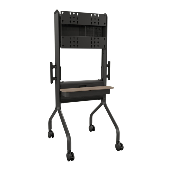
Designer Video Cart
Spanish Product Description
German Product Description
Portuguese Product Description
Italian Product Description
Dutch Product Description
French Product Description
LSCU
Advertisement
Table of Contents

Subscribe to Our Youtube Channel
Related Manuals for LEGRAND CHIEF Voyager Series


Summary of Contents for LEGRAND CHIEF Voyager Series
- Page 1 I N S T A L L A T I O N I N S T R U C T I O N S Instrucciones de instalación Istruzioni di installazione Installationsanleitung Installatie-instructies Instruções de Instalação Instructions d´installation Designer Video Cart Spanish Product Description German Product Description Portuguese Product Description...
-
Page 2: Important Safety Instructions
The information contained in this document is subject to change without notice or obligation of any kind. Legrand makes no representation of warranty, expressed or implied, 175 lbs regarding the information contained herein. -
Page 3: Installation Instructions
Installation Instructions LSCU DIMENSIONS 0 TILT 3° TILT 5° TILT 60.96 1548.4 50.72 1288.4 SECTION A-A SCALE 1 : 5... - Page 4 LSCU Installation Instructions DIMENSIONS - MOUNTING HOLE LOCATIONS...
- Page 5 Installation Instructions LSCU LEGEND Tighten Fastener Pencil Mark Apretar elemento de fijación Marcar con lápiz Befestigungsteil festziehen Stiftmarkierung Apertar fixador Marcar com lápis Serrare il fissaggio Segno a matita Bevestiging vastdraaien Potloodmerkteken Serrez les fixations Marquage au crayon Loosen Fastener Drill Hole Aflojar elemento de fijación Perforar...
-
Page 6: Tools Required For Installation
LSCU Installation Instructions TOOLS REQUIRED FOR INSTALLATION M5 (included) M6 w/ 75mm arm (included) PARTS Hardware Bag A (4) C (4) D (4) B (4) M6x12mm J (2) M6x25mm M8x12mm M6x20mm [Endcap] L (2) [Cable cover] G (8) H (4) E (4) [Universal F (4) -
Page 7: Assembly And Installation
Installation Instructions LSCU Assembly And Installation IMPORTANT ! : The LSCU packaging was designed to help make the installation and setup easier. Do NOT remove assembly prior to reading installation instructions! Cart Assembly Remove all parts and extra packaging from sides of box leaving only the main assembly (N) in the box. - Page 8 LSCU Installation Instructions Install four legs (P and Q) onto two coupler assemblies (U). (See Figure 4) WARNING: Always use two people to move the cart into an NOTE: Legs with brakes (P) may be installed to front or back upright position.
-
Page 9: Display Installation
Installation Instructions LSCU Display Installation WARNING: Always use two people to mount display to cart! WARNING: Exceeding the weight capacity can result in Determine which holes will be used to mount display to cart. serious personal injury or damage to equipment! It is the (See Figure 10) installer’s responsibility to make sure the combined weight of all accessories and components attached to the LSCU head... - Page 10 LSCU Installation Instructions (rear view) (A-F x 4) (tighten) Figure 11 Install display to cart by inserting screws (A-F) into corresponding mounting holes. (See Figure 11) (main faceplate not shown for clarity) IMPORTANT ! : Look through back of cart to make sure all screws are properly seated in mounting holes before letting go of display! Slide locking plate (M) over top of one of the screws (A-F) to...
-
Page 11: Cable Management
Installation Instructions LSCU If desired, break the LeverLock™ backplanes (T) along the Route cables through lower holes on cart as desired. (See scored mid-line. (See Figure 13) Figure 14) Covers Installation NOTE: Before installing any cover, make sure the handle is in the "unlocked"... -
Page 12: Height Adjustment
LSCU Installation Instructions Place small cover (R) in position to install by placing lower Relocate lower screws to appropriate holes on frame based edge along slot that holds cover. (See Figure 17) on desired height. (See Figure 19) Press small cover (R) against cart until it is flush with the cart and is secured in position, (See Figure 17) relocate to maximum setting... -
Page 13: Tilt Adjustment
LSCU Installation Instructions 3° tilt setting 5° tilt setting Figure 21 Tilt Adjustment WARNING RISK OF SERIOUS INJURY OR NOTE: The LSCU cart may be tilted 3° or 5° based on user DEATH! Relocating audio and/or video equipment to furniture preference. - Page 14 LSCU Installation Instructions Push cart using handles Figure 24 Figure 22 Always lock the wheels when the cart is not moving by pressing down the locks on wheels. (See Figure 23) Figure 23 Check and tighten the hex nuts on the casters occasionally. (See Figure 24) These should be checked especially after use on uneven ground.
- Page 15 Installation Instructions LSCU...
- Page 16 Europe A Franklinstraat 14, 6003 DK Weert, Netherlands P +31 (0) 495 580 852 F +31 (0) 495 580 845 8800-003341 Rev01 2022 Legrand Asia Pacific A Office No. 918 on 9/F, Shatin Galleria 18-24 Shan Mei Street www.legrandav.com Fotan, Shatin, Hong Kong...
Need help?
Do you have a question about the CHIEF Voyager Series and is the answer not in the manual?
Questions and answers