
Related Manuals for Ossila T2005


Summary of Contents for Ossila T2005
- Page 1 LED MEASUREMENT SYSTEM USER MANUAL Manual version: 3.0.A Product code: T2005 Product Version: 3.0 Software version: 3.0 enabling materials science Ossila.com...
-
Page 2: Table Of Contents
Taking a Measurement ............................... 21 11. Troubleshooting ............................23 11.1 Installation and Setup ..............................23 11.2 Error Messages and Warnings ........................... 24 12. Related Products ............................25 12.1 Related Consumables ..............................25 12.2 Related Equipment ..............................25 Ossila.com Ossila Limited © 2022... -
Page 3: Overview
User Manual Overview The Ossila LED Measurement System is a low-cost solution for reliable current-voltage-luminance measurements of light emitting diodes. The system is controlled by specially designed software which can perform multiple IVL measurements and measure the current, luminance, and efficiency over long periods of time. -
Page 4: Eu Declaration Of Conformity
Telephone number: +31 (0)71 3322992 Email Address: info@ossila.com declare that the DoC is issued under our sole responsibility and belongs to the following product: Product: Ossila LED Measurement System (T2005A3/T2005B3/T2005C3/T2005E3) Serial number: T2005A3-xxxx, T2005B3-xxxx, T2005C3-xxxx, T2005E3-xxxx Object of declaration: Ossila LED Measurement System (T2005A3/T2005B3/T2005C3/T2003E3) - Page 5 User Manual Декларация за съответствие на ЕС Производител: Ossila BV, Biopartner 3 building, Galileiweg 8, 2333 BD Leiden, NL. Декларира с цялата си отговорност, че посоченото оборудване съответства на приложимото законодателство на ЕС за хармонизиране, посочено на предходната(-ите) страница(-и) на настоящия...
- Page 6 User Manual [Magyar] EU-s megfelelőségi nyilatkozat Gyártó: Ossila BV, Biopartner 3 building, Galileiweg 8, 2333 BD Leiden, NL. Kizárólagos felelösségünk mellett kijelentjük, hogy a felsorolt eszköz megfelel az ezen dokumentum előző oldalán/oldalain található EU-s összehangolt jogszabályok vonatkozó rendelkezéseinek. [Nederlands] EU-Conformiteitsverklaring Fabrikant: Ossila BV, Biopartner 3 building, Galileiweg 8, 2333 BD Leiden, NL.
-
Page 7: Safety
LED Measurement System User Manual Safety Use of Equipment The Ossila LED Measurement System is designed to be used as instructed. It is intended for use under the following conditions: Indoors in a laboratory environment (Pollution Degree 2) • Altitudes up to 2000m •... -
Page 8: Servicing
LED Measurement System User Manual Servicing If servicing is required, please return the unit to Ossila Ltd. The warranty will be invalidated if: Modification or service has been carried out by anyone other than an Ossila engineer. • The Unit has been subjected to chemical damage through improper use. -
Page 9: Requirements
Examine the components for evidence of shipping damage. If damage has occurred, please contact Ossila directly for further action. The shipping packaging will come with a shock indicator to show if there has been any mishandling of the package during transportation. -
Page 10: Specifications
LED Measurement System User Manual Specifications The Ossila LED Measurement System specifications are shown in Table 6.1. Table 6.1. Ossila LED Measurement System specifications. Voltage range ±10 mV to ±10 V Voltage accuracy ±10 mV offset Voltage resolution 170 μV Current range ±10 nA to ±200 mA (5 ranges) -
Page 11: System Components
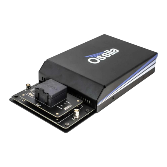
LED Measurement System User Manual System Components The Ossila LED Measurement System is comprised of three items: the Ossila LED Measurement System (Figure 7.1), and the Ossila LED IVL Software (Figure 7.2). Figure 7.1. The Ossila LED Measurement System. Figure 7.2. The Ossila LED IVL software. -
Page 12: Installation
If the unit is not detected, or driver installation fails, please refer to the SMU USB Driver Installation Guide found on the USB memory stick. Note: The Ossila LED IVL software and Source Measure Unit USB drivers can also be downloaded from ossila.com/pages/software-drivers... - Page 13 LED Measurement System User Manual 9.1.1 Characterisation Figure 9.1. Ossila LED IVL software: Characterisation tab. The Characterisation tab is used to perform I-V measurements of LEDs, whilst measuring the illuminance, luminance, white count, and current and power efficiencies using the built-in light sensors.
-
Page 14: Quick Start Guide
Quick Start Guide 1. Start the Ossila LED IVL software. The window shown in Figure 9.1 will open. 2. Choose a measurement type as described in Section 9.1. 3. Place your device in the device holder and close the lid. - Page 15 This defines the upper limit and accuracy of current measurements that can be performed by the unit. The values for each range are given in Table 9.1. Table 9.1. Current range specifications of the Ossila LED Measurement System. Maximum Current...
- Page 16 • (III) Inverted Device Set whether the device to be measured is inverted. • This option should be on if the anode of your device connects to the ‘cathode’ pins in the device holder. Ossila.com Ossila Limited © 2022...
- Page 17 This option performs a reverse current-voltage measurement after the forward current- • voltage measurement has completed. This reverses the set start and end voltages and uses the same voltage increment and settle time as the forward measurement. Ossila.com Ossila Limited © 2022...
- Page 18 Figure 9.7. Controls for saving and loading settings profiles. (I) Save Settings Saves the current settings as a profile that can be loaded quickly for use at another time. • When clicked, you will be prompted to name the settings profile. • Ossila.com Ossila Limited © 2022...
- Page 19 Scroll wheel – scale the axes centred on the cursor location. • A specific axis can be controlled by using these controls on the axis labels. The axes can be reset by clicking the “Reset View” button shown in Figure 9.9. Ossila.com Ossila Limited © 2022...
- Page 20 Warning: Automatic saving can be turned off for lifetime measurements. However, manual saving is unavailable for lifetime measurements, so you will not be able to save your data if it is turned off. Ossila.com Ossila Limited © 2022...
- Page 21 Power Efficiency (lm/W) • The settings used for a measurement are saved to a separate .csv file in a ‘Settings’ folder in the selected save directory. If this folder does not exist, it will be created. Ossila.com Ossila Limited © 2022...
-
Page 22: Test Device
20 μA to 20 μA for the 20 μA current range) as shown in Figure 10.3. 7. To check the calibration of the system, use the I-V data to calculate the measured resistance at -10 and 10 V (-2 and 2 V for the 20 μA current range). Ossila.com Ossila Limited © 2022... - Page 23 III. For all other ranges the calculated resistance should be between 99 and 101 kΩ (within 1% of the resistor value). Figure 10.3. Example measurement of resistor test device using the 200 μA current range. Ossila.com Ossila Limited © 2022...
-
Page 24: Troubleshooting
11. Troubleshooting Most of the issues that may arise will be detailed here. However, if you encounter any issues that are not detailed here, then contact us by email at info@ossila.com. We will respond as soon as possible. 11.1 Installation and Setup... -
Page 25: Error Messages And Warnings
Error saving settings The software does not have the necessary permissions to access the given file path, or the file is already open in other software. Ossila.com Ossila Limited © 2022... -
Page 26: Related Products
Source Measure Unit For removing contamination on the Source voltage, measure current, surface of samples, providing you get data. Simplify and accelerate with ultraclean surfaces within your data collection! minutes. Product code: L2002A2 Product code: P2005A2 Ossila.com Ossila Limited © 2022...
Need help?
Do you have a question about the T2005 and is the answer not in the manual?
Questions and answers