
Related Manuals for Ossila T2006A1


Summary of Contents for Ossila T2006A1
- Page 1 Potentiostat User Manual Manual version 1.2.B Product code: T2006A Product Version 1.0 Software version: 1.0 enabling materials science Ossila.com...
-
Page 3: Table Of Contents
Taking a Measurement ............................... 12 Software Settings and Controls ..........................12 Test Cell Chip ................................20 Performing Cyclic Voltammetry of Ferrocene ......................22 10. Maintenance ............................. 25 11. Troubleshooting ............................26 12. Related Products ............................27 Ossila.com Ossila Limited © 2021... -
Page 4: Overview
Potentiostat User Manual Overview Ossila's Potentiostat is low-cost and easy-to-use system for performing electrochemical measurements, including linear sweep and cyclic voltammetry, open-circuit potential, and controlled potential electrolysis. Cyclic voltammetry is one of the most widely used electrochemical techniques, providing important information about materials including: Reduction and oxidation potentials •... -
Page 5: Eu Declaration Of Conformity (Doc)
Email Address: info@ossila.com declare that the DoC is issued under our sole responsibility and belongs to the following product: Product: Potentiostat (T2006A1), Potentiostat with Cell (T2006B1) Serial number: T2006A- xxxx, T2006B- xxxx Object of declaration Potentiostat (T2006A1) The object of declaration described above is in conformity with... - Page 6 за съответствие на ЕС Производител: Ossila BV, Biopartner 3 building, Galileiweg 8, 2333 BD Leiden, NL. Декларира с цялата си отговорност, че посоченото оборудване съответства на приложимото законодателство на ЕС за хармонизиране, посочено на предходната(- ите) страница(-и) на настоящия документ.
- Page 7 [Suomi] EU-vaatimustenm ukaisuusvakuutus Valmistaja: Ossila BV, Biopartner 3 building, Galileiweg 8, 2333 BD Leiden, NL. Vakuutamme täten olevamme yksin vastuussa siitä, että tässä asiakirjassa luetellut laitteet ovat tämän asiakirjan sivuilla edellisillä sivuilla kuvattujen olennaisten yhdenmukaistamista koskevien EU-säädösten vaatimusten mukaisia. [Svenska] EU-försäkran om överensstämmelse...
-
Page 8: Safety
• DO NOT apply input while not powered. • Use of Equipment The Ossila Potentiostat is designed to be used as instructed. It is intended for use under the following conditions: Indoors in a laboratory environment (Pollution Degree 2) •... -
Page 9: General Hazards
To facilitate disconnect, make sure the power outlet for this cord is readily accessible to the operator. Servicing If servicing is required, please return the unit to Ossila Ltd. The warranty will be invalidated if: Modification or service has taken place by anyone other than an Ossila engineer. •... -
Page 10: Requirements
Examine the components for evidence of shipping damage. If damage has occurred, please contact Ossila directly for further action. The shipping packaging will come with a shock indicator to show if there has been any mishandling of the package during transportation. -
Page 11: Specifications
Current measurement accuracy ±20 nA offset (at 20 μA range) Current measurement resolution 5 nA (at 20 μA range) Communication USB-B Overall Dimensions Width: 125 mm; Height: 55 mm; Depth: 175 mm Weight 600 g Ossila.com Ossila Limited © 2021... -
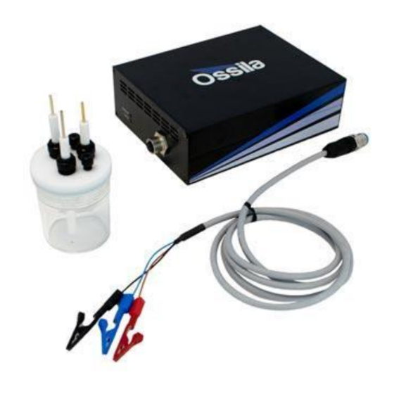
Page 12: System Components
Potentiostat User Manual System Components The Ossila Potentiostat is comprised of 3 items: the Ossila Potentiostat, cell connection cable, and Ossila Electrochemistry software. Figure 7.1. Ossila Potentiostat. Figure 7.2. Cell connection cable. Figure 7.3. Ossila Electrochemistry PC software. Ossila.com Ossila Limited © 2021... -
Page 13: Installation
3. Connect the unit to your PC using the provided USB-B cable. If the unit is not detected, please refer to the SMU USB Driver Installation Guide found on the USB memory stick. Note: The Ossila Electrochemistry software can also be downloaded from https://www.ossila.com/pages/software-drivers. Operation Measurement Types The Electrochemistry software can perform 3 different types of measurement. -
Page 14: Taking A Measurement
II. The black connector goes to the counter electrode. III. The blue connector goes to the reference electrode. 4. Start the Ossila Electrochemistry software. The window shown in Figure 9.1 will open. 5. Enter the appropriate settings for your experiment into the software (explained in more detail in Section 9.3). - Page 15 (IV) Scan Rate (mV/s) The rate at which the potential will be changed during the scan, measured in millivolts per • second. (V) Start Potential (V) The potential in volts at which the measurement starts. • Ossila.com Ossila Limited © 2021...
- Page 16 Start Potential → Potential Vertex 1 → Potential Vertex 2 → Start Potential This will be repeated for the specified number of cycles. Ossila.com Ossila Limited © 2021...
- Page 17 II. To rescan for connected units (in case the connection is changed) click the refresh icon next to the drop-down box. (II) Duration (s) The duration of the measurement in seconds. • Ossila.com Ossila Limited © 2021...
- Page 18 The potential in volts that will be applied during the measurement. • (IV) Duration (s) The duration of the measurement in seconds. • (V) Sampling Period (s) The time between recording data points in seconds. • Ossila.com Ossila Limited © 2021...
- Page 19 Clicking this button will start the measurement using the chosen settings. • This button cannot be clicked if the software has not detected a unit • (II) Abort Stops a measurement that is currently in progress. • Ossila.com Ossila Limited © 2021...
- Page 20 A specific axis can be controlled by using these controls on the axis labels. The axes can be reset by clicking the ‘A’ button in the bottom-left of the plot, as shown in Figure 9.9. Figure 9.9. Button to reset the plot axes. Ossila.com Ossila Limited © 2021...
- Page 21 The program allows for data to be saved automatically, as well as manually once the • measurement is complete. For automatic saving, the ‘Save Directory’ and ‘Sample Name’ fields must be filled in before the measurement can start, these are detailed below. Ossila.com Ossila Limited © 2021...
-
Page 22: Test Cell Chip
Test Cell Chip The Ossila Potentiostat includes a Test Cell Chip, shown in Figure 9.12, which can be used to check that your Potentiostat is operating correctly. It simulates an electrochemical cell by providing a response which differs depending on the direction of the potential scan. - Page 23 II. Black connector to CE. III. Blue connector to RE. 3. Start the Ossila Cyclic Voltammetry software. The window shown in Figure 9.1 will open. 4. In the software enter the settings shown in Figure 9.13. Figure 9.13. Settings for measuring the Test Cell Chip.
-
Page 24: Performing Cyclic Voltammetry Of Ferrocene
Place the cap on the electrochemical cell, then insert the working and counter electrodes into two of the holes. We will now prepare the reference solution; a 0.01 M solution of silver nitrite in acetonitrile. Prepare the solution in a volumetric flask and add it into the reference electrode tube Ossila.com Ossila Limited © 2021... - Page 25 Please allow 30 minutes for the potentiostat to warm up after turning on. Once warmed up, start the Ossila Electrochemistry software and select the “Voltammetry” tab. Ensure that the potentiostat is detected by the software. If it is, the “Connected Systems” drop-down box will be populated, and the “Measure”...
- Page 26 “1”. The full settings used are shown in Figure 9.16. Figure 9.16. Measurement settings for ferrocene. Finally, withdraw the tubing or needle used to degas the cell until it is no longer in the solution, so that it does not interfere with the measurement Ossila.com Ossila Limited © 2021...
-
Page 27: Maintenance
The cell and electrodes should always be thoroughly rinsed immediately after each experiment with the solvent that was used in your electrolyte. Always set the cell to dry, preferably in an oven, before you prepare your electrolyte. This helps reduce contamination of your solution from water. Ossila.com Ossila Limited © 2021... -
Page 28: Troubleshooting
Most of the issues that may arise will be detailed here, however, if there is any issue that isn’t detailed that you encounter then please don’t hesitate to contact us by email, info@ossila.com, and we will respond as soon as possible. -
Page 29: Related Products
12. Related Products Electrochemical Cell for Three Working Electrodes – C2013 Electrode System – C2012 Counter Electrodes – C2014 Reference Electrodes – C2015 Precision Spatulas (Chemical Safe)– Norm-Ject Disposable Luer Lock C161/C162 Syringes – C110 – C116 Ossila.com Ossila Limited © 2021...
Need help?
Do you have a question about the T2006A1 and is the answer not in the manual?
Questions and answers