Advertisement
PROJECT NAME
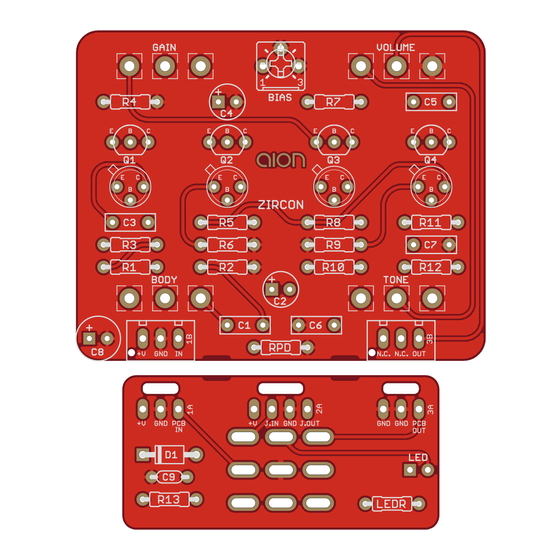
ZIRCON
BASED ON
"Hot Silicon" Tone Bender
EFFECT TYPE
Fuzz / Distortion
PROJECT SUMMARY
An adaptation of the classic Tone Bender Mk. II circuit using silicon transistors and a Big Muff-style tone
control.
Actual size is 2.3" x 1.86" (main board) and 1.78" x 0.87" (bypass board).
ZIRCON SILICON FUZZ
BUILD DIFFICULTY
Easy
DOCUMENT VERSION
1.0.0 (2021-02-19)
1
Advertisement
Table of Contents

Related Manuals for aion ZIRCON SILICON FUZZ


Summary of Contents for aion ZIRCON SILICON FUZZ
- Page 1 1.0.0 (2021-02-19) PROJECT SUMMARY An adaptation of the classic Tone Bender Mk. II circuit using silicon transistors and a Big Muff-style tone control. Actual size is 2.3” x 1.86” (main board) and 1.78” x 0.87” (bypass board). ZIRCON SILICON FUZZ...
-
Page 2: Table Of Contents
10 Document Revisions INTRODUCTION The Zircon Silicon Fuzz is a version of the “Hot Silicon” community project, itself an adaptation of the Sola Sound Tone Bender for silicon transistors. The history of this circuit is a bit suspect, with two people claiming originality. It dates to 2003 at the very latest when Doug Hammond posted a schematic for a circuit he called the Hot Silicon, which was a hybrid of two earlier circuits from Gus Smalley and Aron Nelson. -
Page 3: Parts List
MLCC capacitor, X7R 1N5817 Schottky diode, DO-41 2N5088 BJT transistor, NPN, TO-92 2N5088 BJT transistor, NPN, TO-92 2N5088 BJT transistor, NPN, TO-92 2N5088 BJT transistor, NPN, TO-92 BIAS 5k trimmer Trimmer, 10%, 1/4" See build notes for bias info. ZIRCON SILICON FUZZ... - Page 4 Switchcraft 112BX or equivalent. 1/4" mono 1/4" phone jack, closed frame Switchcraft 111X or equivalent. 2.1mm DC jack, 2.1mm panel mount Mouser 163-4302-E or equivalent. 3PDT Stomp switch, 3PDT 125B Enclosure, die-cast aluminum Can also use a Hammond 1590N1. ZIRCON SILICON FUZZ...
-
Page 5: Build Notes
Two different sets of footprints have been provided for each of the transistors, either standard TO-92 or vintage TO-18 metal can (e.g. 2N2222A). Each outline is connected together on the PCB, so you can use either the top or bottom one in each pair, but not both. ZIRCON SILICON FUZZ... -
Page 6: Schematic
SCHEMATIC 100R 1N5817 100uF 100n BODY 100kA 2N5088 2N5088 100n 2N5088 10uF 2N5088 ZIRCON SILICON FUZZ... -
Page 7: Drill Template
VOLUME GAIN x: -0.65, y: +1.71 x: 0.65, y: +1.71 ø9/32” ø9/32” TONE BODY x: -0.65, y: +0.41 x: 0.65, y: +0.41 ø9/32” ø9/32” CENTER (0,0) FOOTSWITCH x: -0.775, y: -1.20 x: 0, y: -1.20 ø5/16” ø15/32” ZIRCON SILICON FUZZ... -
Page 8: Enclosure Layout
ENCLOSURE LAYOUT Enclosure is shown without jacks. See next page for jack layout and wiring. 125B ZIRCON SILICON FUZZ... -
Page 9: Wiring Diagram
WIRING DIAGRAM N.C. N.C. OUT GND +V +V JACK GND JACK GND GND PCB 125B ZIRCON SILICON FUZZ... -
Page 10: Document Revisions
(In other words: you don’t have to go out of your way to advertise the fact that you use these PCBs, but please don’t go out of your way to hide it. The guitar effects industry needs more transparency, not less!) DOCUMENT REVISIONS 1.0.0 (2021-02-19) Initial release. ZIRCON SILICON FUZZ...
Need help?
Do you have a question about the ZIRCON SILICON FUZZ and is the answer not in the manual?
Questions and answers