Advertisement
Quick Links
Advertisement

Related Manuals for Notifier Honeywell UDS-4N


Summary of Contents for Notifier Honeywell UDS-4N
- Page 1 UDS-4N Extinguishing unit...
- Page 2 7.7 - POSSIBLE CONNECTION DIAGRAMS FOR "EXTINGUISHING SYSTEM IN LOCKOUT" OUTPUT 7.8 - POSSIBLE CONNECTION DIAGRAMS FOR "PILOT CYLINDER/DIRECTIONAL VALVE" OUTPUT 7.9 - WIRING DIAGRAMS FOR CN0 TERMINAL BLOCK OUTPUTS 8 - START-UP UDS-4N Installation and programming INDEX UDS-4N_MANU-INST/PROG. Doc. M-203.1-UDS-4N-ENG Rev A.1 NOTIFIER ITALIA...
-
Page 3: General Description
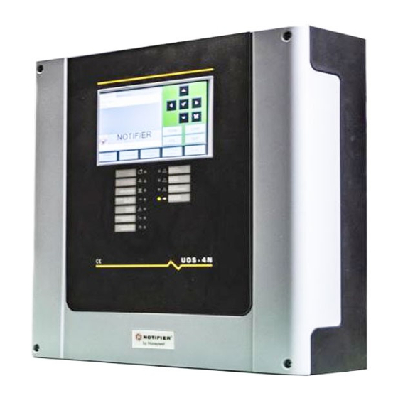
The UDS-4N unit is in a plastic container, equipped with a 7" colour touch display for easy viewing of the system status and protected by passwords at various levels for programming and local management of the shutdown system. Compatible with all NOTIFIER control panels on the market: •... -
Page 4: Electrical Characteristics
This value, placed in series with the batteries, generates a fault within 4 hours. N.B. FOR CONNECTION TO THE DEVICES, USE THE CABLE SPECIFIED IN UNI 9795 STANDARDS. PAGE - 2 Installation and operating manual UDS-4 NOTIFIER ITALIA Doc. M--203.1-UDS4N-ENG Rev A. 1 UDS-4_manu... -
Page 5: Earthing System
Loop A - Loop A + Analogue loop input with isolator Loop B - Loop B + CNSE Name Description Lin+ Non-isolated serial line 485 Lin- UDS-4 Installation and user manual PAGE - 3 UDS-4_manu M--203.1-UDS4N-ENG Rev A.1 NOTIFIER ITALIA... - Page 6 The polarities shown in the tables refer to the "stand-by" condition of the UDS-4N panel. All controlled outputs are protected by a 0.9A self-resetting fuse PAGE - 4 Installation and operating manual UDS-4 NOTIFIER ITALIA Doc. M--203.1-UDS4N-ENG Rev A. 1 UDS-4_manu...
-
Page 7: Description Of Inputs
N.B. The maximum number of devices that can be connected to the line (manual override controls, emergency override and emergency stop controls) depends on the distance from the unit and their power consumption. UDS-4 Installation and user manual PAGE - 5 UDS-4_manu M--203.1-UDS4N-ENG Rev A.1 NOTIFIER ITALIA... - Page 8 This input is used to manage the shutdown cycle, when the UDS-4N goes into the "extinguishing release condition, following the interpretation of the signals from the activation inputs. PAGE - 6 Installation and operating manual UDS-4 NOTIFIER ITALIA Doc. M--203.1-UDS4N-ENG Rev A. 1 UDS-4_manu...
-
Page 9: Description Of Outputs
This output can be excluded from the exclusion menu. N.B. When the SLEEP output is activated, the polarities at the ends of the respective terminals are reversed. UDS-4 Installation and user manual PAGE - 7 UDS-4_manu M--203.1-UDS4N-ENG Rev A.1 NOTIFIER ITALIA... - Page 10 N.B: these six modules have consecutive addresses and only the following addresses are possible: – 10-15, 20-25, 30-35, ..., 90-95, for CLIP module emulation; – 10-15, ..., 90-95, 100-105, 110-15, ..., 150-155, for ADVANCED module emulation. PAGE - 8 Installation and operating manual UDS-4 NOTIFIER ITALIA Doc. M--203.1-UDS4N-ENG Rev A. 1 UDS-4_manu...
- Page 11 GEN_FAULT, EXT_FAULT, AUT_DIS and POW_FAULT. 4 - FRONT PANEL CONTROLS AND SIGNALS Commands are given via the interface on the 7" colour touch display. UDS-4 Installation and user manual PAGE - 9 UDS-4_manu M--203.1-UDS4N-ENG Rev A.1 NOTIFIER ITALIA...
- Page 12 4) each time the switch-off output is reactivated; 5) on the occurrence of any fault condition; 6) when the emergency extension condition occurs; 7) when the emergency stop input is activated. PAGE - 10 Installation and operating manual UDS-4 NOTIFIER ITALIA Doc. M--203.1-UDS4N-ENG Rev A. 1 UDS-4_manu...
- Page 13 Conditions, the Reset is inhibited for a time, in minutes, equal to that set in the "CONF -> Delays -> Reset Delay" parameter. The countdown is not suspended when the emergency extension input is activated. UDS-4 Installation and user manual PAGE - 11 UDS-4_manu M--203.1-UDS4N-ENG Rev A.1 NOTIFIER ITALIA...
- Page 14 Steadily lit when, in the presence of the previous faults, the "Buzzer silencing" key is pressed. VOLTAGE PRESENT Green Permanently lit when the control unit is powered (by mains voltage, 230V or battery). PAGE - 12 Installation and operating manual UDS-4 NOTIFIER ITALIA Doc. M--203.1-UDS4N-ENG Rev A. 1 UDS-4_manu...
- Page 15 Dip-4 = ON: firmware update. JDSPE - A ground fault can be ignored by removing the JDSP jumper. Other Dip positions are for the use of the manufacturer. UDS-4 Installation and user manual PAGE - 13 UDS-4_manu M--203.1-UDS4N-ENG Rev A.1 NOTIFIER ITALIA...
-
Page 16: Operating Conditions
– intermittent activation of the siren/alarm output (0.5s in OFF and 0.5s in ON). PAGE - 14 Installation and operating manual UDS-4 NOTIFIER ITALIA Doc. M--203.1-UDS4N-ENG Rev A. 1 UDS-4_manu... - Page 17 'release output in progress'; – indication in the 'Switch-off' screen of the event related to the 'Extinguishing release condition' by the text 'Switch- off output drive'. UDS-4 Installation and user manual PAGE - 15 UDS-4_manu M--203.1-UDS4N-ENG Rev A.1 NOTIFIER ITALIA...
- Page 18 Only if an activation signal is present in the flow switch input, the UDS-4N will switch to the "release condition" [UNI EN 12094-1 4.15.1]. PAGE - 16 Installation and operating manual UDS-4 NOTIFIER ITALIA Doc. M--203.1-UDS4N-ENG Rev A. 1 UDS-4_manu...
- Page 19 "General fault" LED and the "General fault" output will be activated, and the UDS-4N will go into a safety condition in which it cannot perform any operations. UDS-4 Installation and user manual PAGE - 17 UDS-4_manu M--203.1-UDS4N-ENG Rev A.1 NOTIFIER ITALIA...
- Page 20 N.B.: The use of these parameters is only possible by selecting an address from 10 to 90 in the UDS and selecting the CLIP protocol in the fire alarm control panel. PAGE - 18 Installation and operating manual UDS-4 NOTIFIER ITALIA Doc. M--203.1-UDS4N-ENG Rev A. 1 UDS-4_manu...
- Page 21 If there is no signal from the flow switch, the UDS-4 Installation and user manual PAGE - 19 UDS-4_manu M--203.1-UDS4N-ENG Rev A.1 NOTIFIER ITALIA...
- Page 22 "Manual only shutdown". The "Manual Only" mode places the UDS-4N in the "Manual Only Mode Condition" PAGE - 20 Installation and operating manual UDS-4 NOTIFIER ITALIA Doc. M--203.1-UDS4N-ENG Rev A. 1 UDS-4_manu...
- Page 23 UP and DOWN arrows are used to set the value. A further press of the ENTER key, from the year selection, allows the date to be confirmed. UDS-4 Installation and user manual PAGE - 21 UDS-4_manu M--203.1-UDS4N-ENG Rev A.1 NOTIFIER ITALIA...
- Page 24 USB stick. After insertion, the copying of the event log is started. The end of the copy is indicated by an information window. PAGE - 22 Installation and operating manual UDS-4 NOTIFIER ITALIA Doc. M--203.1-UDS4N-ENG Rev A. 1 UDS-4_manu...
- Page 25 When ENTER is pressed on the "Buzzer" item, the message "Buzzer test in progress" appears on the display and the buzzer is activated first intermittently (0.5s ON, 0.5s OFF) for 3 seconds and then continuously (ON) for 3 seconds UDS-4 Installation and user manual PAGE - 23 UDS-4_manu M--203.1-UDS4N-ENG Rev A.1 NOTIFIER ITALIA...
- Page 26 UDS-4N is in the "Standby condition", activation of the flow switch input brings the UDS-4N into the "Release condition". N.B.: see CONFIGURATION MENU \ Power OFF for more details. PAGE - 24 Installation and operating manual UDS-4 NOTIFIER ITALIA Doc. M--203.1-UDS4N-ENG Rev A. 1 UDS-4_manu...
- Page 27 In the event that an activation signal from the flow switch input puts the UDS-4N into the "Release condition", the siren output will activate even if it was previously disabled. UDS-4 Installation and user manual PAGE - 25 UDS-4_manu M--203.1-UDS4N-ENG Rev A.1 NOTIFIER ITALIA...
- Page 28 The connection of the power supplies must be carried out in accordance with the following steps: PAGE - 26 Installation and operating manual UDS-4 NOTIFIER ITALIA Doc. M--203.1-UDS4N-ENG Rev A. 1 UDS-4_manu...
- Page 29 = 12 V; • nominal capacity = 12 Ah max. BATTERY FIXING The batteries must be inserted inside the control unit, as shown in the figure. UDS-4 Installation and user manual PAGE - 27 UDS-4_manu M--203.1-UDS4N-ENG Rev A.1 NOTIFIER ITALIA...
- Page 30 7.1 - Wiring diagrams for CNL terminal block inputs Name Description Screen printing Loop A - Loop A + Input with analogue loop isolator Loop B - Loop B + PAGE - 28 Installation and operating manual UDS-4 NOTIFIER ITALIA Doc. M--203.1-UDS4N-ENG Rev A. 1 UDS-4_manu...
- Page 31 (controlled entry) Manual shutdown only INMANU (controlled entry) Emergency Interruption Device ININTEM (controlled entry) Pressure switch INPRESS NA,[NA|NC]. (controlled entry) Flow switch INFLUSS NA,[NA|NC]. (controlled entry) UDS-4 Installation and user manual PAGE - 29 UDS-4_manu M--203.1-UDS4N-ENG Rev A.1 NOTIFIER ITALIA...
- Page 32 30V 2A Protection with 0.9A electronic PILOT+ resettable fuse. OFF- Power off [R=2.7 kΩ 1%]. LC at 30V 2A Protection with 0.9A electronic POWER rest resettable fuse. PAGE - 30 Installation and operating manual UDS-4 NOTIFIER ITALIA Doc. M--203.1-UDS4N-ENG Rev A. 1 UDS-4_manu...
- Page 33 Recommended connection Recommended connection for polarised actuators. for non-polarised actuators. Note: The polarities shown in the terminals refer to the "Stand-by" condition of the UDS-4N panel. UDS-4 Installation and user manual PAGE - 31 UDS-4_manu M--203.1-UDS4N-ENG Rev A.1 NOTIFIER ITALIA...
- Page 34 Recommended connection for polarised actuators. for non-polarised actuators. Note: The polarities shown in the terminals refer to the "Stand-by" condition of the UDS-4N panel. PAGE - 32 Installation and operating manual UDS-4 NOTIFIER ITALIA Doc. M--203.1-UDS4N-ENG Rev A. 1 UDS-4_manu...
- Page 35 RL6 / Emergency stop activated 30V 2A NO-NC selectable via J6 INTEM C SCAR NA-NC RL1 / Download event 30V 2A NO-NC selectable via J1 SCAR C UDS-4 Installation and user manual PAGE - 33 UDS-4_manu M--203.1-UDS4N-ENG Rev A.1 NOTIFIER ITALIA...
- Page 36 The signals from the flow switch and the pressure switch are checked to determine whether the switch-off was successful. PAGE - 34 Installation and operating manual UDS-4 NOTIFIER ITALIA Doc. M--203.1-UDS4N-ENG Rev A. 1 UDS-4_manu...
- Page 37 (permanently inhibits release, its deactivation must be followed by the reset command); exclusion of switch-off output (if restored, this implies a new initialisation of the delay). UDS-4 Installation and user manual PAGE - 35 UDS-4_manu M--203.1-UDS4N-ENG Rev A.1 NOTIFIER ITALIA...
- Page 38 To configure the UDS-4N, please refer to the chapter "Programming and testing the UDS4N" in this manual. PAGE - 36 Installation and operating manual UDS-4 NOTIFIER ITALIA Doc. M--203.1-UDS4N-ENG Rev A. 1 UDS-4_manu...
- Page 39 Automatic electrical control device is switch-off and delay management with integrated power supply equipment Compulsory, optional and accessory functions according to applied standards EN 54-4 - EN 12094-1 Notifier Italia Srl - Via Grandi 22 - 20093 San Donato Milanese ( Milan) Compulsory functions (UNI EN 12094-1 4.3) 1) Reception and processing of incoming drive signal from s.r.a.i:...
-
Page 40: Additional Functions
(directional valve/pilot cylinder output). 10) Possibility of completely excluding the management of inputs and outputs for each zone, with a single zone disabling operation. PAGE - 38 Installation and operating manual UDS-4 NOTIFIER ITALIA Doc. M--203.1-UDS4N-ENG Rev A. 1 UDS-4_manu... - Page 41 NOTIFIER ITALIA S.r.l. A socio unico - 20097 San Donato Milanese (Ml) - Via Grandi, 22 - Tel.: 02/518971 - Fax: 02/5189730 - E-mail: notifier@notifier.it Capitale Sociale € 2.700.000,00 i.v. - C.C.A.A. 1456164 - Trib. Milano Reg. Soc. 348608 - Vol. 8549 Fasc. 8 - Partita IVA IT 11319700156 (informativa privacy art. 3...
Need help?
Do you have a question about the Honeywell UDS-4N and is the answer not in the manual?
Questions and answers